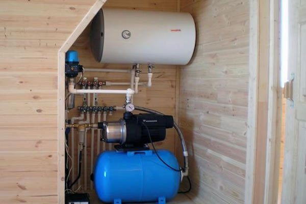

The topic of this article is the calculation of water supply networks in a private house. Since a typical small cottage water supply scheme is not very complex, we do not have to go into the jungle of complex formulas; however, the reader will have to assimilate a certain amount of theory.
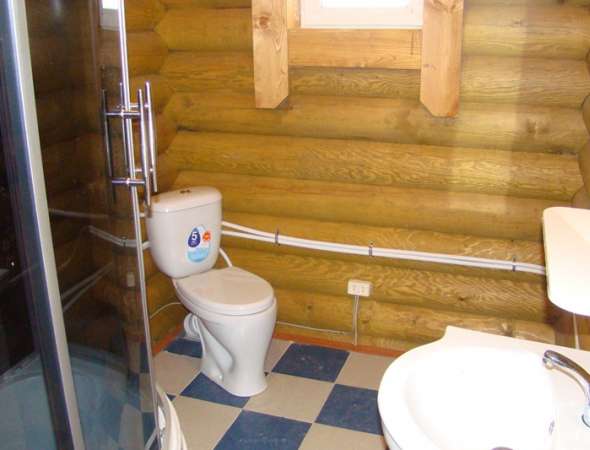
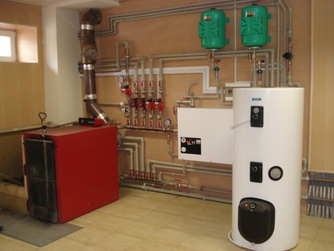
Fragment of the water supply system of a private house. Like any other engineering system, this one needs preliminary calculations.
Features of the wiring of the cottage
What, in fact, is the water supply system in a private house easier than in an apartment building (of course, in addition to the total number of plumbing fixtures)?
There are two fundamental differences:
- With hot water, as a rule, there is no need to provide constant circulation through risers and heated towel rails.
In the presence of circulation inserts, the calculation of the hot water supply network becomes noticeably more complicated: the pipes need to pass through themselves not only the water disassembled by the residents, but also the continuously circulating masses of water.
In our case, the distance from the plumbing fixtures to the boiler, column or tie-in to the line is small enough to ignore the rate of hot water supply to the tap.
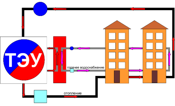
Important: For those who have not come across DHW circulation schemes - in modern apartment buildings, hot water supply risers are connected in pairs. Due to the pressure difference in the tie-ins created by the retaining washer, water is continuously circulated through the risers. This ensures a fast supply of hot water to the mixers and year-round heating of heated towel rails in the bathrooms.
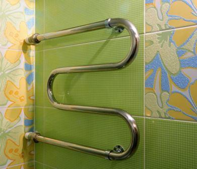
The heated towel rail is heated by continuous circulation through the hot water risers.
- The water supply system in a private house is divided according to a dead-end scheme, which implies a constant load on certain sections of the wiring. For comparison, the calculation of the water supply ring network (allowing each section of the water supply system to be powered from two or more sources) must be performed separately for each of the possible connection schemes.
Calculation of the heat load on the hot water supply. Initial data
This calculation was carried out in order to determine the actual heat load for heating and hot water supply of non-residential premises.
| Customer | Beauty saloon |
| Address of the object | Moscow |
| Heat supply agreement | there is |
| Number of storeys of the building | one-story |
| Floor on which are located surveyed premises | 1st floor |
| Floor height | 2.56 m. |
| Heating system | – |
| Filling type | – |
| Temperature graph | – |
| Estimated temperature graph for the floors on which the rooms are located | – |
| DHW | Centralized |
| Design indoor air temperature | – |
| The presented technical documentation | 1. A copy of the heat supply agreement. 2. A copy of the floor plans. 3. A copy of an extract from the technical passport of the BTI for the building. 4. A copy of the explication of the premises. 5. A copy of the BTI certificate on the condition of the building / room. 6. Certificate of the number of personnel. |
What do we think
We have to:
- Estimate water consumption at peak consumption.
- Calculate the cross-section of the water pipe that can provide this flow rate at an acceptable flow rate.
Note: the maximum water flow rate at which it does not generate hydraulic noise is about 1.5 m / s.
- Calculate the head at the end fixture. If it is unacceptably low, it is worth considering either increasing the diameter of the pipeline, or installing an intermediate pump.

The low pressure on the end mixer is unlikely to please the owner.
The tasks are formulated. Let's get started.
Consumption
It can be roughly estimated by the consumption rates for individual plumbing fixtures. Data, if desired, can be easily found in one of the annexes to SNiP 2.04.01-85; for the convenience of the reader, we present an excerpt from it.
| Device type | Cold water consumption, l / s | Total consumption of hot and cold water, l / s |
| Watering tap | 0,3 | 0,3 |
| Toilet bowl with a tap | 1,4 | 1,4 |
| Toilet bowl with cistern | 0,10 | 0,10 |
| Shower cubicle | 0,08 | 0,12 |
| Bath | 0,17 | 0,25 |
| Washing | 0,08 | 0,12 |
| Washbasin | 0,08 | 0,12 |
In apartment buildings, when calculating the consumption, the probability coefficient of the simultaneous use of devices is used. It is enough for us to simply sum up the water consumption through devices that can be used at the same time. Let's say a sink, a shower stall and a toilet bowl will give a total flow of 0.12 + 0.12 + 0.10 = 0.34 l / s.
Water consumption through devices capable of operating simultaneously is summed up.
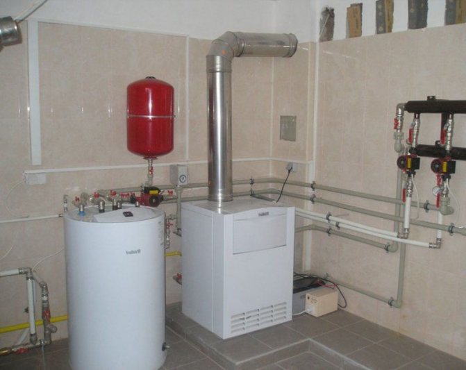
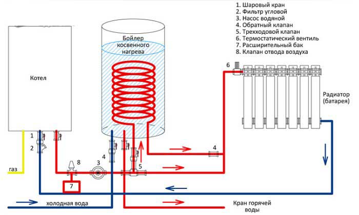
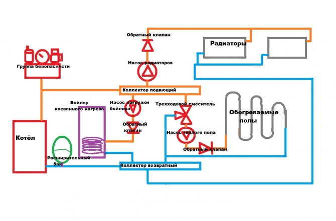
Boiler heating time
Boiler heating circuit.
The temperature of hot water in the boiler can be adjusted from the control panel in the range of 30-80 ° C. But, as mentioned earlier, you should not set the temperature above 65 ° C in order to eliminate the risk of burns. To achieve the optimal temperature for taking a bath or washing dishes, you need to mix water from the boiler with cold water, the average temperature of which ranges from 15 ° C in winter and summer, respectively. On average, a water heater heats 100 liters to 60 ° C for about 5 hours. At the same time, when mixed with cold water, 185-250 liters of liquid with a comfortable temperature in summer and 160-215 liters - in winter are obtained. Of course, the real values differ from the calculations, since as the hot water decreases, cold water is added to the boiler tank, which means that the total water temperature decreases.
Cross section
Calculation of the cross-section of a water supply pipe can be performed in two ways:
- Selection according to the table of values.
- Calculated according to the maximum permissible flow rate.
Selection by table
Actually, the table does not require any comments.
| Nominal pipe bore, mm | Consumption, l / s |
| 10 | 0,12 |
| 15 | 0,36 |
| 20 | 0,72 |
| 25 | 1,44 |
| 32 | 2,4 |
| 40 | 3,6 |
| 50 | 6 |
For example, for a flow rate of 0.34 l / s, a DU15 pipe is sufficient.
Please note: DN (nominal bore) is approximately equal to the inner diameter of the water and gas pipe. For polymer pipes marked with an outer diameter, the inner one differs from it by about a step: say, a 40 mm polypropylene pipe has an inner diameter of about 32 mm.
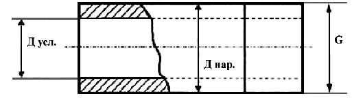
The nominal bore is approximately equal to the inner diameter.
Flow rate calculation
Calculation of the diameter of the water supply system by the flow rate of water through it can be performed using two simple formulas:
- Formulas for calculating the area of a section along its radius.
- Formulas for calculating the flow rate through a known section at a known flow rate.
The first formula is S = π r ^ 2. In it:
- S is the required cross-sectional area.
- π is pi (approximately 3.1415).
- r is the section radius (half of the DN or the inner diameter of the pipe).
The second formula looks like Q = VS, where:
- Q - consumption;
- V is the flow rate;
- S - cross-sectional area.
For the convenience of calculations, all values are converted to SI - meters, square meters, meters per second and cubic meters per second.
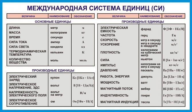
SI units.
Let's calculate with our own hands the minimum DU of the pipe for the following input data:
- The flow through it is all the same 0.34 liters per second.
- The flow velocity used in the calculations is the maximum allowable 1.5 m / s.
Let's get started.
- The flow rate in SI values will be equal to 0.00034 m3 / s.
- The sectional area according to the second formula must be at least 0.00034 / 1.5 = 0.00027 m2.
- The square of the radius according to the first formula is 0.00027 / 3.1415 = 0.000086.
- Take the square root of this number. The radius is 0.0092 meters.
- To get DN or inner diameter, multiply the radius by two. The result is 0.0184 meters, or 18 millimeters. As you can easily see, it is close to that obtained by the first method, although it does not exactly coincide with it.
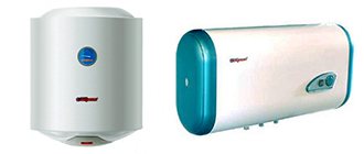
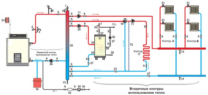
Device and principle of operation
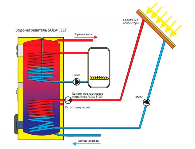
Indirect heating boilers are devices that accumulate hot water from an external heating device. Such equipment does not have a heating element in its design.
The main feature of the device is the presence of a heat exchanger, through the tubes of which a coolant circulates, heated to a certain temperature by the boiler. It is usually made in the form of a coil to increase the heat dissipation surface.
The tank for these devices is made in two layers, inside of which there is thermal insulation that performs several functions:
- Reduction of heat losses,
- Protecting people from burns,
- Improving the strength characteristics of equipment.
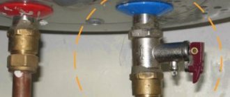
Temperature control is ensured by a built-in thermostat, and a safety valve protects the device from pressure drops. Most models of this equipment are equipped with a magnesium anode, which protects the inner surface from the appearance and action of corrosion.
Often, manufacturers of heating equipment develop and produce a series of devices that ideally interact in tandem boiler-boiler. But there are also universal water heating equipment suitable for most types of boilers.
Pressure
Let's start with a few general notes:
- Typical pressure in the cold water supply line is from 2 to 4 atmospheres (kgf / cm2)... It depends on the distance to the nearest pumping station or water tower, on the terrain, the state of the mains, the type of valves on the main water supply and a number of other factors.
- The absolute minimum pressure that allows all modern plumbing fixtures and household appliances using water to work is 3 meters... The instruction for Atmor instantaneous water heaters, for example, directly says that the lower response threshold of the pressure sensor that includes heating is 0.3 kgf / cm2.

The pressure sensor of the device is triggered at a pressure of 3 meters.
Reference: at atmospheric pressure, 10 meters of head corresponds to 1 kgf / cm2 overpressure.
In practice, on an end fixture, it is better to have a minimum head of five meters. A small margin compensates for unaccounted for losses in connections, shut-off valves and the device itself.
We need to calculate the head drop in a pipeline of known length and diameter. If the difference in pressure corresponding to the pressure in the main line and the drop in pressure in the water supply system is more than 5 meters, our water supply system will function flawlessly. If it is less, you need to either increase the diameter of the pipe, or open it by pumping (the price of which, by the way, will clearly exceed the increase in costs for pipes due to an increase in their diameter by one step).
So how is the calculation of the pressure in the water supply network carried out?
Here the formula H = iL (1 + K) is valid, in which:
- H is the coveted value of the pressure drop.
- i is the so-called hydraulic slope of the pipeline.
- L is the length of the pipe.
- K is a coefficient that is determined by the functionality of the water supply system.
The easiest way is to determine the K.
It is equal to:
- 0.3 for household and drinking purposes.
- 0.2 for industrial or fire-fighting.
- 0.15 for fire and production.
- 0.10 for a firefighter.
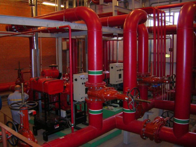
In the photo there is a fire water supply system.
There are no particular difficulties with measuring the length of the pipeline or its section; but the concept of hydraulic bias requires a separate discussion.
Its value is influenced by the following factors:
- The roughness of the pipe walls, which, in turn, depends on their material and age. Plastics have a smoother surface than steel or cast iron; in addition, steel pipes become overgrown with limescale deposits and rust over time.
- Pipe diameter. The inverse relationship operates here: the smaller it is, the more resistance the pipeline has to the movement of water in it.
- Flow rate. With its increase, the resistance also increases.
Some time ago, it was necessary to additionally take into account hydraulic losses on valves; however, modern full bore ball valves create roughly the same resistance as a pipe and can therefore be safely ignored.
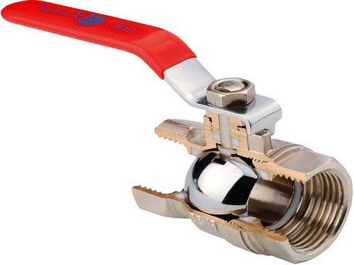
An open ball valve has almost no resistance to the flow of water.
Calculating the hydraulic slope on your own is very problematic, but, fortunately, this is not necessary: all the necessary values can be found in the so-called Shevelev tables.
To give the reader an idea of what is at stake, we present a small fragment of one of the tables for a plastic pipe with a diameter of 20 mm.
| Consumption, l / s | Flow speed, m / s | 1000i |
| 0,25 | 1,24 | 160,5 |
| 0,30 | 1,49 | 221,8 |
| 0,35 | 1,74 | 291,6 |
| 0,40 | 1,99 | 369,5 |
What is the 1000i in the far right column of the table? This is just the hydraulic slope value per 1000 linear meters. To get the value of i for our formula, it is enough to divide it by 1000.
Let's calculate the pressure drop in a pipe with a diameter of 20 mm with its length equal to 25 meters and a flow rate of one and a half meters per second.
- We are looking for the corresponding parameters in the table. According to her data, 1000i for the described conditions is 221.8; i = 221.8 / 1000 = 0.2218.
Shevelev's tables have been reprinted many times since the first publication.
- Substitute all values into the formula. H = 0.2218 * 25 * (1 + 0.3) = 7.2085 meters. With a pressure at the inlet of the water supply system of 2.5 atmospheres at the outlet, it will be 2.5 - (7.2 / 10) = 1.78 kgf / cm2, which is more than satisfactory.
What is the waiting period and how is it calculated
The waiting period is the time that elapses from the time the user opens the tap until hot water is dispensed. They try to reduce this time as much as possible, for this, the hot water supply system is optimized, corrections are made, and if the performance is poor, they are modernized.
Generally accepted standards are used to set the waiting period. To calculate it correctly, you should know the following:
- To reduce the waiting period, high water pressure should be created in the system. But setting too high the pressure parameters can damage the pipeline.
- To reduce the waiting period, increase the throughput of the device through which the user receives fluid.
- The waiting period increases in direct proportion to the internal diameter of the pipeline, as well as in the presence of a circuit at a great distance from the consumer.
The correct sequence for calculating the waiting period is:
- Determination of the number of consumers. After the exact figure, a small margin should be made, as there are peak hot water consumption.
- Determination of the characteristics of the pipeline: length, inner diameter of pipes, as well as the material from which they are made.
- The multiplication of the length of the pipeline and its internal diameter by the specific volume of water, which is measured in l / s.
- Determination of the shortest and most convenient fluid path. This parameter also includes the sections of the contour that are located farthest from the water-folding device. The addition of all volumes of water is also performed.
- The amount of liquid is divided by the water flow rate in one second. When obtaining this parameter, the total fluid pressure in the system is also taken into account.
To achieve the most accurate results, you should correctly calculate the specific volume of the pipeline. For this, the following formula is applied:
Cs = 10 • (F / 100) 2 • 3.14 / 4, where F is the internal diameter of the pipeline.
When determining the specific volume, the value of both the outer and the nominal pipe diameter cannot be used. This will significantly reduce the accuracy of the calculations. There are tables in which the value of the specific volume is calculated in advance for certain materials (copper and steel).