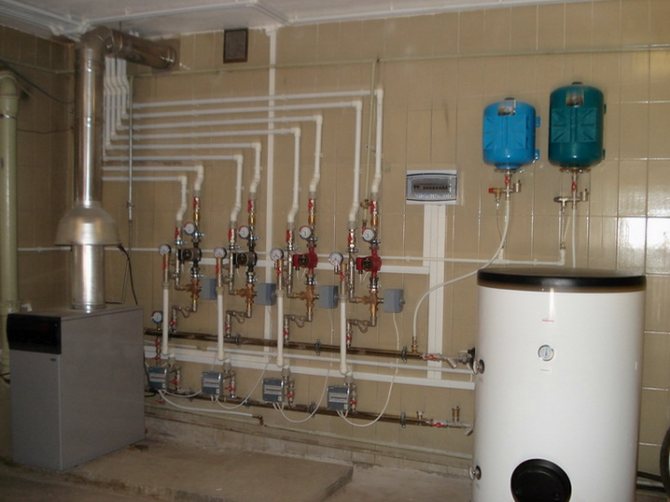
Features of the installation of gas boilers and furnace equipment
The installation of gas boilers must be carried out in accordance with the requirements of regulatory documents. The tenants themselves, the owners of the building cannot install gas equipment. It should be installed in accordance with a project that can only be developed by an organization licensed to do so.
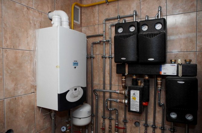
Gas boilers are also installed (connected) by specialists from a licensed organization. Trading companies, as a rule, have permits for after-sales service of automated gas equipment, often for design and installation. Therefore, it is convenient to use the services of one organization.
Below, for informational purposes, the basic requirements for the places where boilers operating on natural gas can be installed (connected to the gas main) are given. But the construction of such structures must be carried out in accordance with the project and the requirements of the standards.
Different requirements for boilers with a closed and open combustion chamber
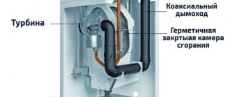
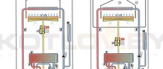
All boilers are classified according to the type of combustion chamber and the way it is ventilated. The closed combustion chamber is ventilated forcibly using a fan built into the boiler.
This allows you to do without a high chimney, but only with a horizontal section of the pipe and take air for the burner from the street through an air duct or the same chimney (coaxial chimney).
Therefore, the requirements for the installation site of one low-power (up to 30 kW) wall-mounted boiler with a closed combustion chamber are not so stringent. It can be installed in a dry utility room, including the kitchen.
Installation of gas equipment in living rooms is prohibited, in the bathroom is prohibited
Boilers with an open burner are another matter. They work for a high chimney (above the ridge of the roof), which creates a natural draft through the combustion chamber. And the air is taken directly from the room.
The presence of such a combustion chamber entails the main limitation - these boilers must be installed in separate rooms specially allocated for them - furnace (boiler rooms).
Learn more about the features of boilers with different combustion chambers. And also learn about choosing an economical boiler and creating an economical heating system.
Next, we will consider in more detail the requirements for the placement of boilers within the furnace, and for this room.
Where can the furnace (boiler room) be located
The room for the installation of boilers can be located on any floor of a private house, including in the basement and basement, as well as in the attic and on the roof.
Those. under the furnace, you can adapt a room within the house with dimensions not less than the standard, the doors from which lead to the street. And also equipped with a window and a ventilation grill of a certain area, etc. The furnace can be located in a separate building.
What and how can be placed in the furnace
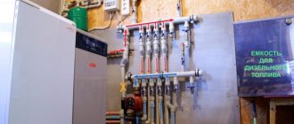
The free passage from the front side of the installed gas equipment must be at least 1 meter wide. The furnace can accommodate up to 4 units of gas heating equipment with closed combustion chambers, but with a total capacity of no more than 200 kW.
Furnace dimensions
The height of the ceilings in the furnace (boiler room) is not less than 2.2 meters, the floor area is not less than 4 square meters. for one boiler.But the volume of the furnace is regulated depending on the capacity of the installed gas equipment: - up to 30 kW inclusive - not less than 7.5 cubic meters; - 30 - 60 kW inclusively - not less than 13.5 cubic meters; - 60 - 200 kW - at least 15 cubic meters
What is equipped with a furnace
The furnace is equipped with doors to the street with a width of at least 0.8 meters, as well as a window for natural lighting with an area of at least 0.3 square meters. 10 cubic meters. furnace.
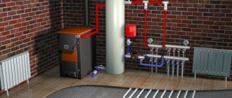
The furnace is supplied with a single-phase 220 V power supply, made in accordance with the PUE, as well as a water supply system connected to heating and hot water supply, as well as a sewage system that can receive water in case of emergency flooding, including in the volumes of a boiler and a buffer tank.
The presence in the boiler room of combustible, fire hazardous materials, including finishing on the walls, is not allowed. The gas main within the furnace must be equipped with a shut-off device, one for each boiler.
How the furnace (boiler room) should be ventilated
The furnace must be equipped with exhaust ventilation, possibly connected to the ventilation system of the entire building. Fresh air can be supplied to the boilers through the ventilation grill, which is installed at the bottom of the door or wall.
Moreover, the area of the holes in this grate should not be less than 8 cm square per one kilowatt of boiler power. And if the inflow from inside the building is at least 30 cm square. for 1 kW.
Chimney
The values of the minimum diameter of the chimney depending on the boiler output are given in the table.
But the basic rule is this - the cross-sectional area of the chimney should not be less than the area of the outlet in the boiler.
Each chimney must have an inspection hole located at least 25 cm below the chimney inlet.
For stable operation, the chimney must be above the roof ridge. Also, the chimney trunk (vertical part) must be absolutely straight.
This information is provided for informational purposes only to form a general idea of the furnace in private houses. When building a room for placing gas equipment, it is necessary to be guided by design solutions and the requirements of regulatory documents.
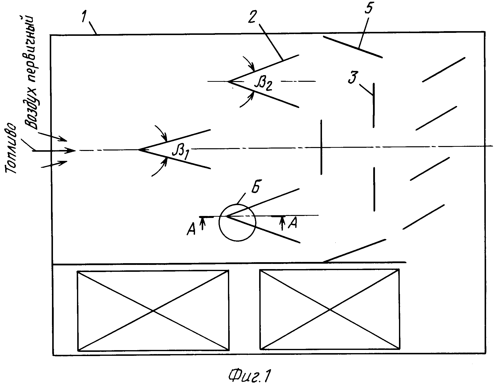
Determination of the dimensions of the combustion chamber, convection flue and placement of burners
The combustion chamber of the designed boiler is a parallelepiped (at - width, bt - depth, ht - height)
The volume of the combustion chamber is limited by the axial plane of the wall and ceiling wall tubes. The section of the furnace along the axes of the pipes of the screens fт is determined on the basis of the heat release density tested in practice along the section of the furnace qf
fт =, m2 (9)
The width and depth of the combustion chamber are selected based on the dimensions of the flame of the burners and their heat output. The course project uses Weishaupt [] automatic burners. The dimensions of the section of the combustion chamber are determined according to the nomogram in Figure 9.1.
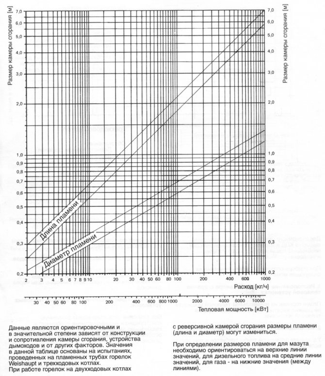
Figure 9.1
Heat output of the burner
, kW (9.1)
where Вр is the volumetric consumption of natural gas, m3 / h;
- the lowest heat of combustion of gas, kJ / m3.
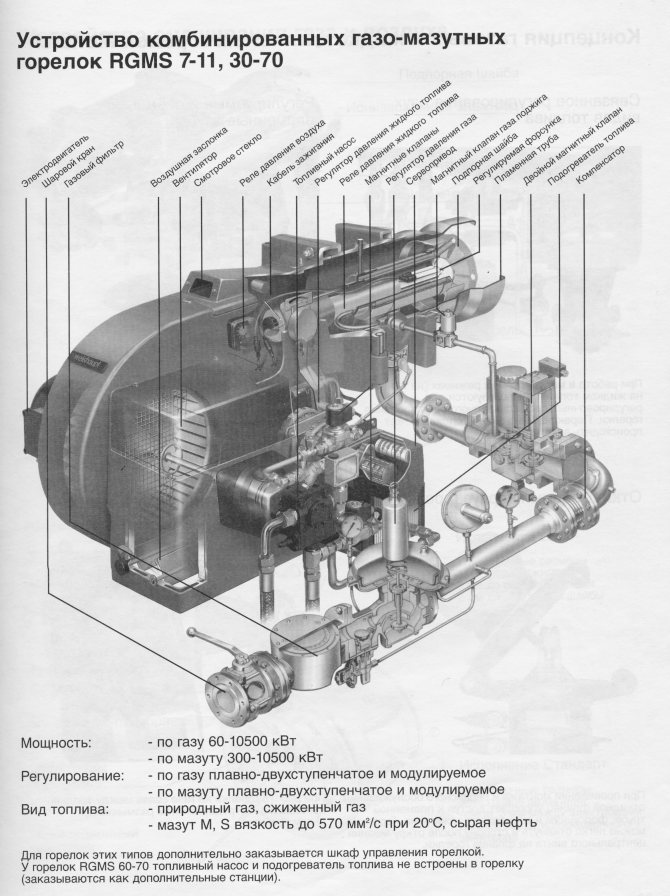
In boilers with low productivity (up to 25 t / h), one burner is installed per boiler. The type of suitable burner is selected from the catalog [].
The result of the choice of the burner is presented in table. 9.1
Table 9.1
| Burner type | number |
| Monarh gas-oil 1000 ... 1000 kW |
The volume of the boiler combustion chamber is selected based on the permissible thermal stress of the combustion volume.
, m3 (9.2)
The results of calculating the section, volume and height of the combustion chamber are presented in table. 9.2
Table 9.2
| , m3 / s | , kJ / m3 | , kW / m2 | , m2 | , kW / m2 | , m3 | ht, m |
The smallest section of the convective gas duct is determined based on the volume of gases at the entrance to the mine and on their economically optimal speed
, m2 (9.3)
where Fk is the section, m2; - temperature of flue gases at the entrance to the gas duct, оС; K is the coefficient of the free flow area; - optimal speed of flue gases, m / s.
Free flow area ratio
, (9.4)
where S1 is the pipe pitch in the cross-section transverse to the gas flow, mm; d - outer diameter of pipes, mm.
S1 S1 d
gas flow
Pre-selected d = 51 mm, S1 = 100 mm. The calculation results are presented in table. 9.3
Table 9.3
| , m3 / h | , m3 / s | Vg, m3 / m3 | , oC | , m / s | S, mm | d, mm | TO | , m2 |
The calculated surface of the walls of the combustion chamber
, m2 (9.5)
Estimated volume of the combustion chamber
, m3 (9.6)
The result of the determination is presented in table. 9.4
Table 9.4
| , m | , m | , m | , m2 | , m2 |
Thermal calculation of the combustion chamber
10.1. Useful heat dissipation in the firebox
, kJ / m3 (10)
where is the net calorific value of dry natural gas, kJ / m3; - the heat of the outside air. Since cold air is not preheated
, kJ / m3 (10.1)
The calculation results are given in table. 10.1
Table 10.1
| , kJ / m3 | , % | , kJ / m3 | , kJ / m3 | , kJ / m3 |
Theoretical (adiabatic) fuel combustion temperature.
Temperature, υa is determined from the table. 7.3 by interpolating the enthalpy of the combustion chamber gases using the formula
, оС (10.2)
The calculation result is presented in table. 10.2
Table 10.2
| , kJ / m3 | , оС | , оС | , kJ / m3 | , kJ / m3 | , оС |
Differences between gas and water tube boilers according to the scheme of work
A container that allows you to create steam is usually made from one or more pipes. The water found in them is warmed up by the heated gases released during the combustion of the fuel. This design implies that the gas itself rises to the pipes filled with water, and devices operating on this principle are called gas-tube boilers.
In another type of boilers, gas moves through a pipe in the very container with water. The capacity in this case is called a drum, and the boiler itself belongs to the water tube category. The drums filled with water can be located horizontally, vertically, radially or in combination, depending on which the corresponding types of water tube boilers are distinguished.
Comparison of the features of the considered types of boilers allows us to draw the following conclusions:
- The first difference is the different sizes of the pipes used. Gas-tube devices are equipped with rather large pipes compared to products that are used in water-tube boilers.
- The next difference is the power difference. The maximum power value of gas-tube boilers is 360 kW, and the maximum pressure cannot exceed 1 MPa. High pressure and steam volume require an increase in the wall thickness of the device, which negatively affects the final cost of the boiler. Water-tube boilers are devoid of such a drawback - thin pipes can be used for them, allowing them to achieve higher temperature and pressure compared to gas-tube counterparts.
- Water tube boilers differ not only in power and higher temperatures. Their advantages also include the ability to withstand serious overloads, which indicates a greater degree of safety of such devices.
Reasons for a drop in vacuum in the boiler furnace and ways to solve the problem
A drop below the minimum threshold of 9-10 Pa is considered critical, with it there may be problems with combustion, the ingress of unburned fuel, products of its combustion into the room. If we exclude errors in the design of the combustion chamber and the boiler itself, the reasons for the drop in vacuum in the boiler furnace are usually simple and easily fixable:
- Chimney clogged... Both large objects that enter the chimney from the street and natural soot formation, inherent not only in solid fuel, but also in any other (gas, liquid fuel, combined) boilers, can block the exhaust of combustion products, increase friction and narrow the diameter of the chimney. To eliminate the problem, you need to thoroughly clean the chimney from soot and ash using a metal brush on a long wire, any suitable scrapers, circles that almost correspond to the diameter of the chimney and other suitable tools. Even with the normal technical condition of the heating equipment and favorable operating conditions, it is recommended that the chimney be cleaned annually before the start of the heating season.
- Insulation problems... Insufficient thermal insulation of the chimney or its absence leads to a strong decrease in the difference in temperatures between the atmosphere and flue gases, which, accordingly, reduces the difference in air density (rarefaction).
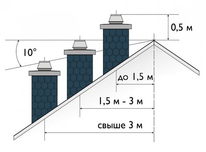
- Errors in the design of the chimney... Most often, mistakes are made in determining the height of the chimney (common and its street part). To ensure normal draft, the total height of the chimney must be at least 5 meters. The norms in relation to the jumping of the roof of the house are shown in the photo below.

The optimal chimney height is according to SNiP 41-01-2003. - Deflector damage. The deflector on the chimney headband contributes to a more optimal direction of wind and exhaust gas flows, respectively, if its design is violated, the properties are lost.
It is also important to understand that the vacuum can be unstable and insufficient if the temperature difference in the combustion chamber and the atmosphere is not so significant, for example, in relatively warm times outside the heating season when the boiler is operating in the minimum temperature mode.
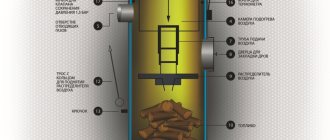
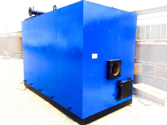
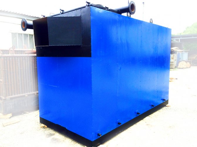
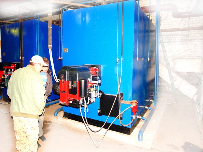
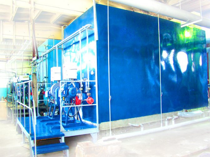
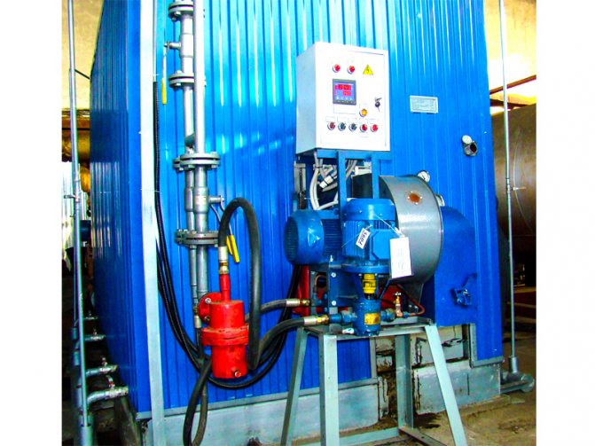
3.1. Steam boiler MZK-7AG
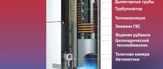
The vertical-cylindrical steam boiler MZK-7AG of the Moscow Boiler Plant is a boiler with natural circulation. The boiler consists of an upper (Fig. 3.1) and a lower annular collectors, interconnected by vertical pipes arranged along concentric circles in a staggered manner. The inner ring row forms a cylindrical combustion chamber. The pitch of the pipes ensures their fastening in the tube sheets by rolling or welding. To ensure the operation of the boiler under pressurization at an excess pressure of 200 ... 500 Pa (20 ... 50 kgf / m2), the combustion chamber is made gas-tight due to the use of fin pipes welded together along the fins.
Shielding pipes, between which steam generators exit, are installed more rarely and do not have fins. The radiation surface of the furnace and the subsequent rows of pipes, forming a convective surface, are made of pipes with an outer diameter of 38 mm.
The upper annular manifold has a removable cover allowing access for inspection, cleaning and repair of heating surfaces and manifolds. The lower annular manifold is formed by a lower tube sheet and a stamped stop ring. Feed water enters the upper collector, descends through less heated convection pipes into the lower collector, and the resulting steam-water mixture enters the upper collector through waterwall pipes, where steam is separated from water.
Steam is removed from the upper header through a steam shut-off valve installed on the boiler cover. There are also two spring-loaded safety valves. On the side surface of the upper manifold, two water indicating devices and a pressure gauge are installed. The boiler is purged from the lower annular chamber through the valve
The boiler is equipped with a feed pump and a blower fan. The combustion air is supplied by the fan through the branch pipe to the annular air channel formed by the internal heat-resistant and external shells, which is at the same time the thermal insulation of the boiler. Heated air from the annular channel through the air duct and air register 8 is supplied to the boiler burner. On the. In the air register, a rotary damper is provided for on-off regulation of the flow rate of the air supplied to the burner, depending on the fuel flow rate.
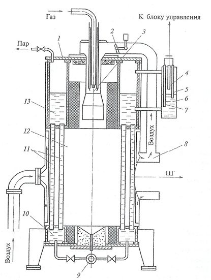
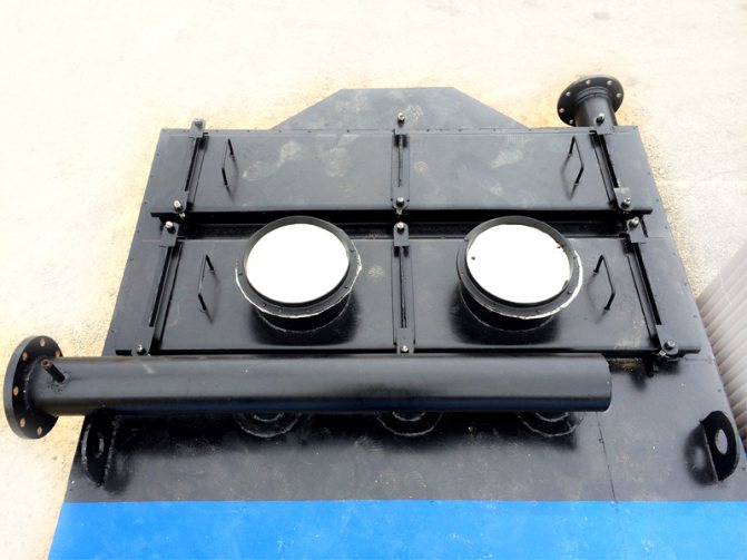
Fig. 3.1. Steam boiler MZK-7AG:
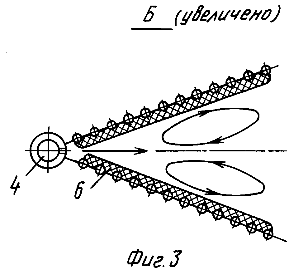
cap; rotary damper; burner; 4, 5, 7 electrodes, respectively, of the upper, lower emergency water levels; level gauge column; air register; boiler blowdown valve; 10, 13 lower and upper annular collectors; - pipes; combustion chamber
The short-flare mixing gas burner consists of a central tube through which gas is supplied, an ignition device and two electrodes.Combustion products through two windows formed by pipes diverge in two streams along a ring-shaped gas duct in opposite directions. Washing convective pipes on their way, the SG flows are connected on the side opposite to the inlet and are diverted into the chimney.