Calculation of the heat exchanger currently takes no more than five minutes. Any organization that manufactures and sells such equipment, as a rule, provides everyone with its own selection program. You can download it for free from the company's website, or their technician will come to your office and install it for free. However, how correct is the result of such calculations, is it possible to trust it and is the manufacturer not cunning when fighting in a tender with its competitors? Checking an electronic calculator requires knowledge or at least an understanding of the calculation methodology for modern heat exchangers. Let's try to figure out the details.
What is a heat exchanger
Before calculating the heat exchanger, let's remember, what kind of device is it? A heat and mass exchange apparatus (aka a heat exchanger, aka a heat exchanger, or TOA) is a device for transferring heat from one heat carrier to another. In the process of changing the temperatures of the coolants, their densities and, accordingly, the mass indicators of substances also change. That is why such processes are called heat and mass transfer.
Calculation of a plate heat exchanger
The data of the coolants in the technical design of the equipment must be known. These data should include: physical and chemical properties, flow rate and temperatures (initial and final). If the data of one of the parameters are not known, then it is determined using thermal calculation.
Thermal calculation is intended to determine the main characteristics of the device, among which are: coolant flow rate, heat transfer coefficient, heat load, average temperature difference. All these parameters are found using heat balance.
Let's take a look at an example of a general calculation.
In the heat exchanger apparatus, heat energy circulates from one stream to another. This happens during heating or cooling.
Q = Qg = Qx
Q - the amount of heat transmitted or received by the heat carrier [W],
Where from:
Qг = Gгсг · (tгн - tгк) and Qх = Gхcх · (tхк - tхн)
Where:
Gr, x - consumption of hot and cold heat carriers [kg / h]; cr, x - heat capacity of hot and cold heat carriers [J / kg · deg]; tg, xn - initial temperature of hot and cold heat carriers [° C]; tr, x k - final temperature of hot and cold heat transfer agents [° C];
At the same time, keep in mind that the amount of incoming and outgoing heat largely depends on the state of the coolant. If the state is stable during operation, then the calculation is made according to the formula above. If at least one coolant changes its state of aggregation, then the calculation of the incoming and outgoing heat should be done according to the formula below:
Q = Gcp (tp - tsat) + Gr + Gcp (tsat - ts)
Where:
r - heat of condensation [J / kg]; cn, k - specific heat capacities of steam and condensate [J / kg · deg]; tк- condensate temperature at the outlet of the apparatus [° C].
The first and third terms should be excluded from the right side of the formula if the condensate is not cooled. By excluding these parameters, the formula will have the following expression:
Qmountains
= Qcond= Gr
Thanks to this formula, we determine the flow rate of the coolant:
Gmountains
= Q / cmountains(tgn- tgk) or Gcold= Q / ccold(thk- then)
The formula for the consumption, if heating is by steam:
Gpair = Q / Gr
Where:
G - consumption of the corresponding heat carrier [kg / h]; Q - the amount of heat [W]; from - specific heat capacity of heat carriers [J / kg · deg]; r - heat of condensation [J / kg]; tg, xn - initial temperature of hot and cold heat carriers [° C]; tg, x k - end temperature of hot and cold heat transfer agents [° C].
The main force of heat transfer is the difference between its components. This is due to the fact that passing the coolants, the flow temperature changes, in connection with this, the temperature difference indicators also change, so for calculations it is worth using the average value. The temperature difference in both directions of travel can be calculated using the log mean:
∆tav = (∆tb - ∆tm) / ln (∆tb / ∆tm) Where ∆tb, ∆tm- larger and smaller average temperature difference between the coolants at the inlet and outlet of the apparatus. Determination with cross and mixed flow of heat carriers occurs according to the same formula with the addition of a correction factor ∆tav = ∆tavfref ... The heat transfer coefficient can be determined as follows:
1 / k = 1 / α1 + δst / λst + 1 / α2 + Rzag
in the equation:
δst- wall thickness [mm]; λst- coefficient of thermal conductivity of the wall material [W / m · deg]; α1,2 - heat transfer coefficients of the inner and outer sides of the wall [W / m2 · deg]; Rzag - coefficient of wall contamination.
Types of heat transfer
Now let's talk about the types of heat transfer - there are only three of them. Radiation - the transfer of heat through radiation. As an example, you can think of sunbathing on the beach on a warm summer day. And such heat exchangers can even be found on the market (tube air heaters). However, most often for heating living quarters, rooms in an apartment, we buy oil or electric radiators. This is an example of another type of heat transfer - convection. Convection can be natural, forced (exhaust hood, and there is a recuperator in the box) or mechanically induced (with a fan, for example). The latter type is much more efficient.
However, the most efficient way of transferring heat is thermal conductivity, or, as it is also called, conduction (from the English conduction - "conduction"). Any engineer who is going to conduct a thermal calculation of a heat exchanger, first of all, thinks about choosing efficient equipment in the smallest possible dimensions. And this is achieved precisely due to thermal conductivity. An example of this is the most efficient TOA today - plate heat exchangers. Plate TOA, according to the definition, is a heat exchanger that transfers heat from one heat carrier to another through the wall separating them. The maximum possible contact area between two media, together with correctly selected materials, the profile of the plates and their thickness, allows you to minimize the size of the selected equipment while maintaining the original technical characteristics required in the technological process.
Varieties of heat exchangers for hot water systems
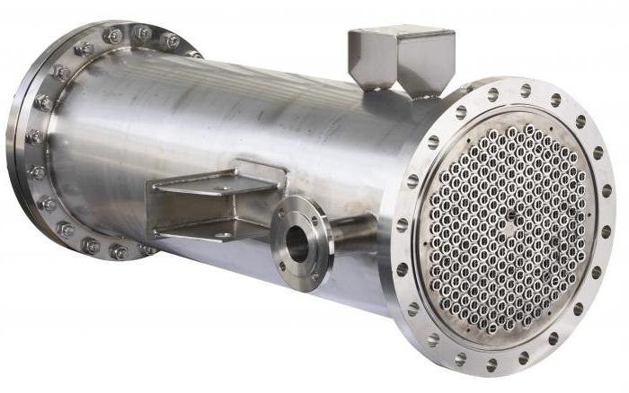
Today there are many of them, but among all the most popular for use in everyday life are two: these are shell-and-tube and plate-type systems. It should be noted that shell-and-tube systems have almost disappeared from the market due to their low efficiency and large size.
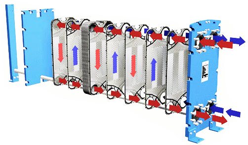
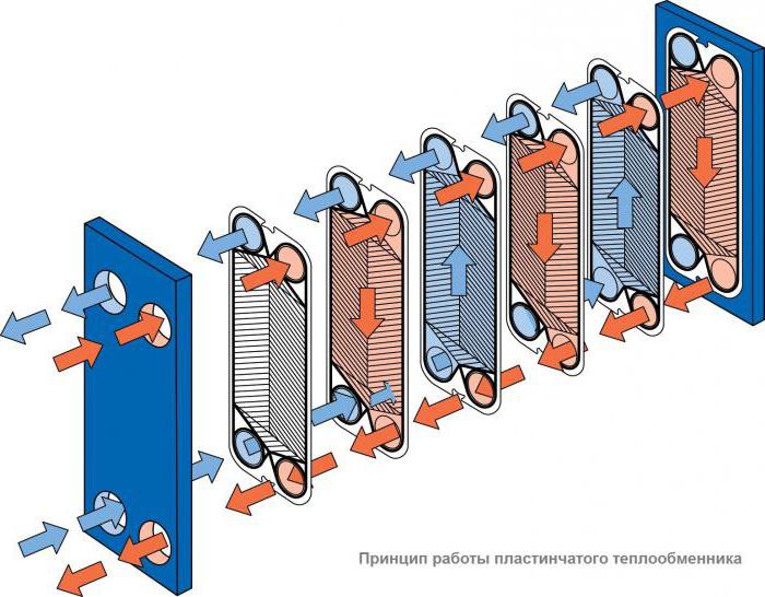
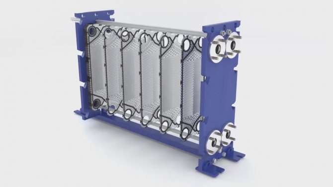
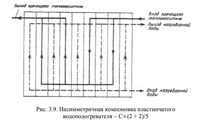
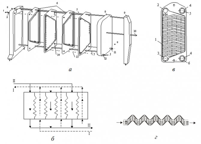
A plate-type heat exchanger for hot water supply consists of several corrugated plates located on a rigid frame. They are identical to each other in design and dimensions, but follow each other, but according to the principle of mirror reflection, and are divided among themselves by specialized gaskets. The gaskets can be either steel or rubber.
Due to the alternation of plates in pairs, such cavities appear, which during operation are filled either with a liquid for heating or a heat carrier. It is due to this design and the principle of operation that the displacement of the media between each other is completely excluded.
By means of the guide channels, the liquids in the heat exchanger move towards each other, filling the even cavities, after which they leave the structure, having received or given off some of the heat energy.
Scheme and principle of operation of the DHW plate heat exchanger
The more plates in number and size there will be in one heat exchanger, the more area it will be able to cover, and the greater will be its performance and useful action during operation.
For some models, there is a space on the track beam between the striker plate and the bed. It is enough to install a couple of slabs of the same type and size. In this case, additional tiles will be installed in pairs.
All plate-type heat exchangers can be divided into several categories:
- 1. Brazed, that is, non-separable and having a sealed main body.
- 2. Collapsible, that is, consisting of several separate tiles.
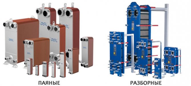
The main advantage and plus of working with collapsible structures is that they can be modified, modernized and improved, from there to remove excess or add new plates. As for brazed designs, they do not have such a function.
However, the most popular today are brazed heat supply systems, and their popularity is based on the lack of clamping elements. Thanks to this, they are compact in size, which does not affect the usefulness and performance in any way.
Heat exchanger types
Before calculating the heat exchanger, they are determined with its type. All TOA can be divided into two large groups: recuperative and regenerative heat exchangers. The main difference between them is as follows: in recuperative TOA, heat exchange occurs through a wall separating two coolants, and in regenerative TOA, the two media have direct contact with each other, often mixing and requiring subsequent separation in special separators. Regenerative heat exchangers are divided into mixing and heat exchangers with packing (stationary, falling or intermediate). Roughly speaking, a bucket of hot water exposed to frost or a glass of hot tea placed in the refrigerator to cool (never do that!) Is an example of such a mixing TOA. And by pouring tea into a saucer and cooling it in this way, we get an example of a regenerative heat exchanger with a nozzle (the saucer in this example plays the role of a nozzle), which first contacts the ambient air and takes its temperature, and then takes some of the heat from the hot tea poured into it. , seeking to bring both media into thermal equilibrium. However, as we have already found out earlier, it is more efficient to use thermal conductivity to transfer heat from one medium to another, therefore, TOA that are more useful in terms of heat transfer (and widely used) today are, of course, recuperative.
Thermal and structural calculation
Any calculation of a recuperative heat exchanger can be made based on the results of thermal, hydraulic and strength calculations. They are fundamental, mandatory in the design of new equipment and form the basis of the calculation method for subsequent models of the line of the same type of apparatus. The main task of the thermal calculation of TOA is to determine the required area of the heat exchange surface for stable operation of the heat exchanger and maintaining the required parameters of the media at the outlet. Quite often, in such calculations, engineers are given arbitrary values of the mass and size characteristics of the future equipment (material, pipe diameter, plate dimensions, beam geometry, type and material of finning, etc.), therefore, after the thermal one, a constructive calculation of the heat exchanger is usually carried out.Indeed, if at the first stage the engineer calculated the required surface area for a given pipe diameter, for example, 60 mm, and the length of the heat exchanger thus turned out to be about sixty meters, then it is more logical to assume a transition to a multi-pass heat exchanger, or to a shell-and-tube type, or to increase the diameter of the tubes.
Hydraulic calculation
Hydraulic or hydromechanical, as well as aerodynamic calculations are carried out in order to determine and optimize the hydraulic (aerodynamic) pressure losses in the heat exchanger, as well as to calculate the energy costs to overcome them. The calculation of any path, channel or pipe for the passage of the coolant poses a primary task for a person - to intensify the heat transfer process in this area. That is, one medium should transmit, and the other should receive as much heat as possible at the minimum interval of its flow. For this, an additional heat exchange surface is often used, in the form of a developed surface ribbing (to separate the boundary laminar sublayer and enhance flow turbulization). The optimal balance ratio of hydraulic losses, heat exchange surface area, weight and size characteristics and removed heat power is the result of a combination of thermal, hydraulic and constructive calculation of TOA.
Calculation of the average temperature difference
The heat exchange surface is calculated when determining the required amount of heat energy by means of heat balance.
The calculation of the required heat exchange surface is carried out using the same formula as in the calculations carried out earlier:
The temperature of the working media, as a rule, changes during the course of processes associated with heat exchange. That is, the change in the temperature difference along the heat exchange surface will be recorded. Therefore, the average temperature difference is calculated. Due to the nonlinearity of the temperature change, the logarithmic difference is calculated
The counter-current movement of working media differs from the direct-flow one in that the required area of the heat exchange surface in this case should be less. To calculate the difference in temperature indicators when using in the same course of the heat exchanger and counter-current and direct-flow flows, the following formula is used
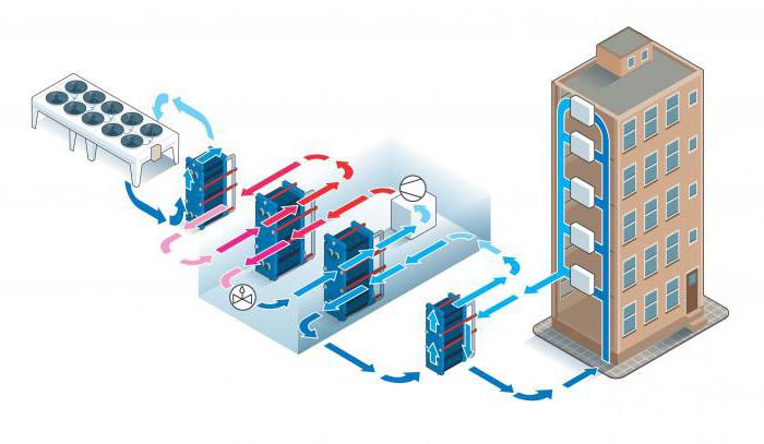
The main purpose of the calculation is to calculate the required heat exchange surface area. Thermal power is set in the terms of reference, but in our example we will also calculate it in order to check the terms of reference itself. In some cases, it also happens that there may be an error in the original information. Finding and fixing such an error is one of the tasks of a competent engineer. The use of this approach is very often associated with the construction of skyscrapers in order to relieve pressure of equipment.
Verification calculation
Calculation of the heat exchanger is carried out in the case when it is necessary to lay a margin for power or for the area of the heat exchange surface. The surface is reserved for various reasons and in different situations: if this is required according to the terms of reference, if the manufacturer decides to add an additional margin in order to be sure that such a heat exchanger will go into operation, and to minimize errors made in the calculations. In some cases, redundancy is required to round off the results of design dimensions, in others (evaporators, economizers), a surface margin is specially introduced into the calculation of the heat exchanger's capacity for contamination with compressor oil present in the refrigeration circuit. And the low quality of water must be taken into account.After some time of uninterrupted operation of heat exchangers, especially at high temperatures, scale settles on the heat exchange surface of the apparatus, reducing the heat transfer coefficient and inevitably leading to a parasitic decrease in heat removal. Therefore, a competent engineer, when calculating the water-to-water heat exchanger, pays special attention to additional redundancy of the heat exchange surface. The verification calculation is also carried out in order to see how the selected equipment will work in other, secondary modes. For example, in central air conditioners (air supply units), first and second heating heaters, used in the cold season, are often used in the summer to cool the incoming air by supplying cold water to the tubes of the air heat exchanger. How they will function and what parameters they will give out allows you to evaluate the verification calculation.
Heat exchanger calculation method (surface area)
So, we have calculated parameters such as the amount of heat (Q) and the heat transfer coefficient (K). For the final calculation, you will additionally need a temperature difference (tav) and a heat transfer coefficient.
The final formula for calculating a plate heat exchanger (heat transfer surface area) looks like this:
In this formula:
- the values of Q and K are described above;
- tav value (average temperature difference) is obtained by the formula (arithmetic mean or logarithmic mean);
- heat transfer coefficients are obtained in two ways: either using empirical formulas, or through the Nusselt number (Nu) using similarity equations.
Research calculations
Research calculations of TOA are carried out on the basis of the obtained results of thermal and verification calculations. As a rule, they are necessary for making the latest amendments to the design of the projected apparatus. They are also carried out in order to correct any equations laid down in the implemented calculation model TOA, obtained empirically (according to experimental data). Performing research calculations involves tens, and sometimes hundreds of calculations according to a special plan developed and implemented in production according to the mathematical theory of experiment planning. According to the results, the influence of various conditions and physical quantities on the performance indicators of TOA is revealed.
Other calculations
When calculating the area of the heat exchanger, do not forget about the resistance of materials. The TOA strength calculations include checking the designed unit for stress, for torsion, for applying the maximum permissible operating moments to the parts and assemblies of the future heat exchanger. With minimal dimensions, the product must be durable, stable and guarantee safe operation in various, even the most stressful operating conditions.
Dynamic calculation is carried out in order to determine the various characteristics of the heat exchanger at variable modes of its operation.
Tube-in-tube heat exchangers
Let's consider the simplest calculation of a pipe-in-pipe heat exchanger. Structurally, this type of TOA is simplified as much as possible. As a rule, a hot coolant is allowed into the inner pipe of the apparatus to minimize losses, and a cooling coolant is launched into the casing, or into the outer pipe. The task of the engineer in this case is reduced to determining the length of such a heat exchanger based on the calculated area of the heat exchange surface and given diameters.
It should be added here that the concept of an ideal heat exchanger is introduced in thermodynamics, that is, an apparatus of infinite length, where the coolants work in a counterflow, and the temperature difference is fully triggered between them. The tube-in-tube design comes closest to meeting these requirements.And if you run the coolants in a counterflow, then it will be the so-called "real counterflow" (and not crossflow, as in plate TOA). The temperature head is most efficiently triggered with such an organization of movement. However, when calculating a pipe-in-pipe heat exchanger, one should be realistic and not forget about the logistics component, as well as the ease of installation. The length of the eurotruck is 13.5 meters, and not all technical rooms are adapted to the skidding and installation of equipment of this length.
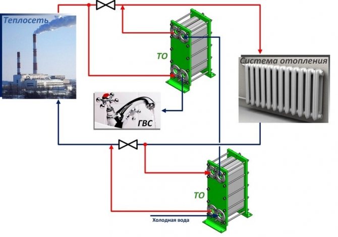
Heat exchanger for the heating system. 5 tips for the right selection.
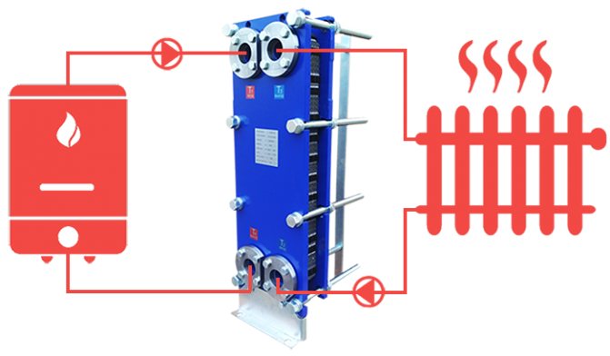
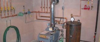
A heat exchanger for heating is an equipment in which heat exchange takes place between a heating and a heated heat carrier. The heating medium comes from a heat source, which is a heating network or a boiler. The heated coolant circulates between the heat exchanger and heating devices (radiators, underfloor heating, etc.)
The task of this heat exchanger is to transfer heat from a heat source to heating devices that directly heat the room. The heat source circuit and the heat consumer circuit are hydraulically separated - the heat carriers do not mix. Most often, water and glycol mixtures are used as working heat carriers.
The principle of operation of a plate heat exchanger for heating is quite simple. Consider an example where the heat source is a hot water boiler. In the boiler, the heating medium heats up to a predetermined temperature, then the circulation pump supplies this coolant to the plate heat exchanger. The plate heat exchanger consists of a set of plates. The heating coolant, flowing through the channels of the plate on one side, transfers its heat to the heated coolant, which flows from the other side of the plate. As a result, the heated coolant increases its temperature to the calculated value and enters the heating devices (for example, radiators), which already give off heat to the heated room.
For any room with hot water heating, the heat exchanger is an important link in the system. Therefore, this equipment has found wide application in the installation of heating points, air heating, radiator heating, underfloor heating, etc.
The first step in the design of a heating system is to determine the heating load, i.e. what power do we need a heat source. The heating load is determined based on the area and volume of the building, while taking into account the heat loss of the building through all the enclosing structures. In simple situations, you can use a simplified rule - 1 kW is needed for 10m2 of area. power, with standard walls and a ceiling height of 2.7 m. Further, it is necessary to determine the schedule according to which our heat source (boiler) will work. These data are indicated in the boiler passport, for example, the coolant supply is 90C and the coolant return is 70C. Taking into account the temperature of the heating medium, we can set the temperature of the heated heating medium - 80C. With this temperature, it will enter the heating devices.
An example of calculating a heating heat exchanger
So, you have the heating load and the temperatures of the heating and heating circuits. This data is already enough for a specialist to be able to calculate a heat exchanger for your heating system. We want to give some advice, thanks to which you can provide us with more complete technical information for the calculation. Knowing all the subtleties of your technical task, we will be able to offer the most optimal variant of the heat exchanger.
- Need to know if residential or non-residential premises need to be heated?
- When the quality of the water is poor, and there are impurities in it, which settle on the surface of the plates and impair heat transfer.You should take into account the margin (10% -20%) on the heat exchange surface, this will increase the price of the heat exchanger, but you will be able to operate the heat exchanger normally without overpaying for the heating coolant.
- When calculating, you also need to know what type of heating system will be used. For example, for a warm floor, the heated coolant has a temperature of 35-45C, for radiator heating 60C-90C.
- What will be the source of heat - your own boiler or heating networks?
- Do you plan to further increase the capacity of the heat exchanger? For example, you plan to complete the building and the heated area will increase.
These are some examples of price and lead time plate heat exchangers that we supplied to our customers in 2019.
1. Plate heat exchanger НН 04, price - 19,200 rubles, production time 1 day. Power - 15 kW. Heating circuit - 105C / 70C Heated circuit - 60C / 80C
2. Plate heat exchanger НН 04, price - 22,600 rubles, production time 1 day. Power - 30 kW. Heating circuit - 105C / 70C Heated circuit - 60C / 80C
3. Plate heat exchanger НН 04, price - 32,500 rubles, production time 1 day. Power - 80 kW. Heating circuit - 105C / 70C Heated circuit - 60C / 80C
4. Plate heat exchanger НН 14, price - 49 800 rubles, production time 1 day. Power - 150 kW. Heating circuit - 105C / 70C Heated circuit - 60C / 80C
5. Plate heat exchanger nn 14, price - 63,000 rubles, production time 1 day. Power - 300 kW. Heating circuit - 105C / 70C Heated circuit - 60C / 80C
6. Plate heat exchanger НН 14, price - 83,500 rubles, production time 1 day. Power - 500 kW. Heating circuit - 105C / 70C Heated circuit - 60C / 80C
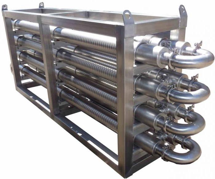
Shell and tube heat exchangers
Therefore, very often the calculation of such an apparatus smoothly flows into the calculation of a shell-and-tube heat exchanger. This is an apparatus in which a bundle of pipes is located in a single housing (casing), washed by various coolants, depending on the purpose of the equipment. In condensers, for example, the refrigerant is run into the jacket and the water into the pipes. With this method of moving media, it is more convenient and more effective to control the operation of the apparatus. In evaporators, on the contrary, the refrigerant boils in the tubes, and at the same time they are washed by the cooled liquid (water, brines, glycols, etc.). Therefore, the calculation of a shell-and-tube heat exchanger is reduced to minimizing the size of the equipment. While playing with the diameter of the casing, the diameter and number of inner pipes and the length of the apparatus, the engineer reaches the calculated value of the area of the heat exchange surface.
Calculation of heat exchangers and various methods of compiling a heat balance
When calculating heat exchangers, internal and external methods of compiling a heat balance can be used. The internal method uses heat capacities. With the external method, the values of specific enthalpies are used.
When using the internal method, the heat load is calculated using different formulas, depending on the nature of the heat exchange processes.
If heat exchange occurs without any chemical and phase transformations, and, accordingly, without the release or absorption of heat.
Accordingly, the heat load is calculated by the formula
If in the process of heat exchange there is a condensation of steam or evaporation of a liquid, any chemical reactions occur, then a different form is used to calculate the heat balance.
When using an external method, the calculation of the heat balance is based on the fact that an equal amount of heat enters and exits the heat exchanger for a certain unit of time. If the internal method uses data on heat exchange processes in the unit itself, then the external method uses data from external indicators.
To calculate the heat balance using the external method, the formula is used.
Q1 means the amount of heat that enters and leaves the unit per unit of time. This means the enthalpy of substances that enter and leave the unit.
You can also calculate the difference in enthalpies in order to establish the amount of heat that has been transferred between different media. For this, a formula is used.
If, in the process of heat exchange, any chemical or phase transformations have occurred, the formula is used.
Air heat exchangers
One of the most common heat exchangers today is finned tubular heat exchangers. They are also called coils. Wherever they are not installed, starting from fan coil units (from the English fan + coil, ie "fan" + "coil") in the internal blocks of split systems and ending with giant flue gas recuperators (heat extraction from hot flue gas and transfer it for heating needs) in boiler plants at CHP. That is why the design of a coil heat exchanger depends on the application where the heat exchanger will go into operation. Industrial air coolers (VOPs), installed in blast freezing chambers of meat, in freezers of low temperatures and at other objects of food refrigeration, require certain design features in their performance. The distance between the lamellas (ribs) should be as large as possible to increase the continuous operation time between defrost cycles. Evaporators for data centers (data processing centers), on the contrary, are made as compact as possible, keeping spacing to a minimum. Such heat exchangers operate in "clean zones" surrounded by fine filters (up to the HEPA class), therefore, such a calculation of the tubular heat exchanger is carried out with an emphasis on minimizing the size.
Plate heat exchangers
Currently, plate heat exchangers are in stable demand. According to their design, they are completely collapsible and semi-welded, copper-brazed and nickel-brazed, welded and brazed by the diffusion method (without solder). The thermal design of a plate heat exchanger is flexible enough and not particularly difficult for an engineer. In the selection process, you can play with the type of plates, the punching depth of the channels, the type of ribbing, the thickness of steel, different materials, and most importantly - numerous standard-size models of devices of different dimensions. Such heat exchangers are low and wide (for steam heating of water) or high and narrow (separating heat exchangers for air conditioning systems). They are often used for phase change media, that is, as condensers, evaporators, desuperheaters, pre-condensers, etc. It is a little more difficult to carry out the thermal calculation of a heat exchanger operating according to a two-phase scheme than a liquid-liquid heat exchanger, but for an experienced engineer, this task is solvable and not particularly difficult. To facilitate such calculations, modern designers use engineering computer bases, where you can find a lot of necessary information, including diagrams of the state of any refrigerant in any scan, for example, the CoolPack program.
First, we will consider what heat exchangers are, and then we will consider the formulas for calculating heat exchangers. And Tables of different heat exchangers by capacity.
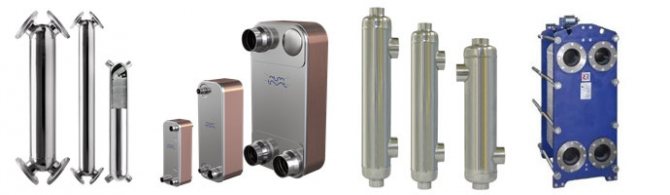
Brazed heat exchanger AlfaLaval - non-separable!
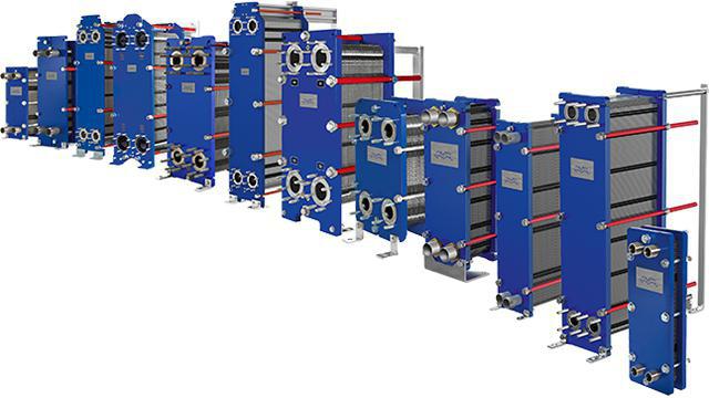
AlfaLaval - Dismountable with rubber gaskets
The main purpose of this type of heat exchanger is the instantaneous transfer of temperature from one independent circuit to another. This makes it possible to get heat from the central heating to its own independent heating system. It also makes it possible to receive hot water supply.
There are collapsible and non-collapsible heat exchangers! AlfaLaval
- Russian production!
Brazed heat exchanger AlfaLaval - non-separable!
Design
Brazed stainless steel heat exchangers do not require gaskets or pressure plates. The solder connects the plates securely at all contact points for optimal heat transfer efficiency and high pressure resistance. The design of the plates is designed for a long service life. PPTs are very compact, since heat transfer occurs through almost all of the material from which they are made. They are lightweight and have a small internal volume. Alfa Laval offers a wide range of devices that can always be tailored to specific customer requirements. Any problems related to heat exchange are solved by the PPH in the most efficient way from an economic point of view.
Material
The brazed plate heat exchanger consists of thin corrugated stainless steel plates, vacuum-brazed together using copper or nickel as solder. Copper brazed heat exchangers are most often used in heating or air conditioning systems, while nickel brazed heat exchangers are mainly intended for the food industry and for handling corrosive liquids.
Mixing protection
In cases where the rules of operation or for other reasons require increased safety, you can use the patented designs of the brazed heat exchangers with double walls. In these heat exchangers, the two media are separated from each other by a double stainless steel plate. In the event of an internal leak, it can be seen on the outside of the heat exchanger, but mixing of the media in any case will not occur.
AlfaLaval - Dismountable with rubber gaskets
Heat exchanger: Liquid - liquid
1-plate; 2-tie bolts; 3,4-front and rear massive slab; 5-branch pipes for connection of the heating circuit; 6-branch pipes for connecting pipelines of the heating system.
Appointment
Get a separate closed (independent) heating circuit of the heating system, while receiving only heat energy. Flow and pressure are not transmitted. Thermal energy is transferred due to the transfer of temperature by heat transfer plates on different sides of which a heat carrier flows (giving off heat and receiving heat). This makes it possible to isolate your heating system from the central heating network. There may be other tasks as well.
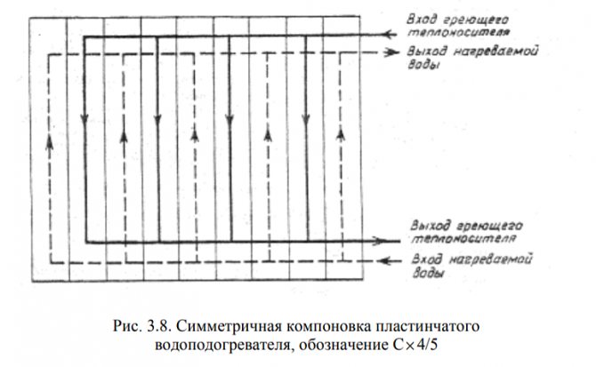
1-supply pipe for heat supply; 2-return pipe for heat release; 3-return pipe for receiving heat; 4-supply pipe for receiving heat; 5-channel for receiving heat; 6-channel for heat release. The arrows indicate the direction of movement of the coolant.
Keep in mind that there are other modifications of heat exchangers in which the pipes of one circuit do not cross diagonally, but run vertically!
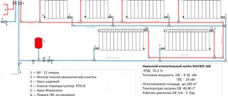
Heating system diagram
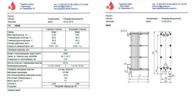
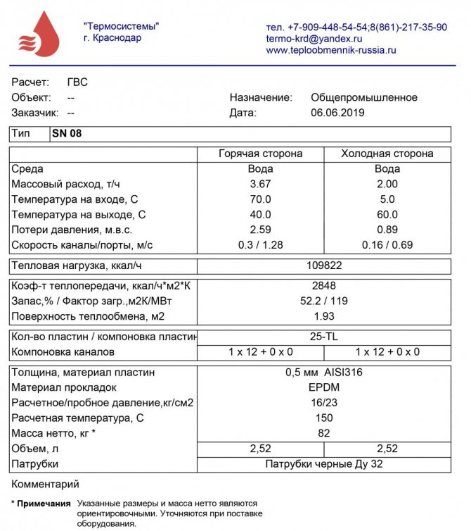
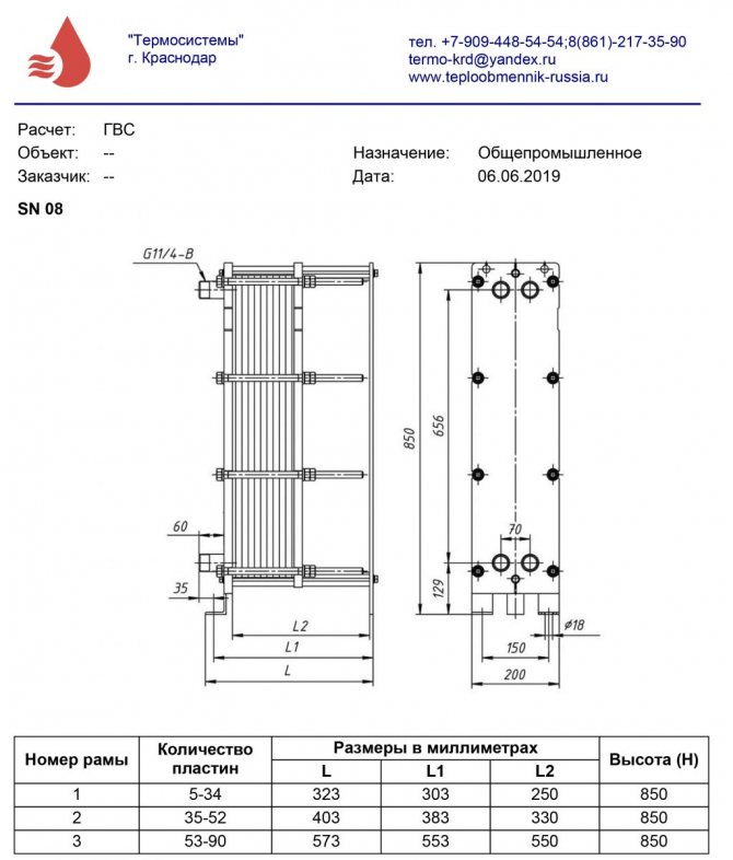
Each plate heat exchanger has the values that are required for the calculation.
The efficiency (efficiency) of the heat exchanger can be found by the formula
In practice, these values are 80-85%.
What should be the costs through the heat exchanger?
Consider the scheme
There are two independent circuits on opposite sides of the heat exchanger, which means that the flow rates of these circuits can be different.
To find the costs, you need to know how much heat energy is required for heating the second circuit.
For example, it will be 10 kW.
Now you need to calculate the required area of the plates for transferring thermal energy using this formula
Total heat transfer coefficient
To solve the problem, you need to get acquainted with some types of heat exchangers, and on their basis, analyze the calculations of such heat exchangers.
Advice!
You will not be able to independently calculate the heat exchanger for one simple reason. All data that characterize the heat exchanger are hidden from unauthorized persons. It is difficult to find the heat transfer coefficient from the actual flow rate! And if the flow rate is deliberately small, then the efficiency of the heat exchanger will not be sufficient!
An increase in power with a decrease in flow leads to an increase in the heat exchanger itself by 3-4 times in the number of plates.
Each manufacturer of heat exchangers has a special program that selects a heat exchanger.
The higher the heat transfer coefficient, the faster this coefficient becomes lower due to scale deposits!
Recommendations for the selection of PHE in the design of heat supply facilities
What are the manufacturers of heat exchangers silent about? O contamination of heat exchangers
Column "Heat carrier" - circuit 1 of the heat source.
Column "Medium to be heated" - circuit 2.
Watch in high resolution!
| Like |
| Share this |
| Comments (1) (+) [Read / Add] |
All about the country house Water supply Training course. Automatic water supply with your own hands. For Dummies. Malfunctions of the downhole automatic water supply system. Water supply wells Well repair? Find out if you need it! Where to drill a well - outside or inside? In what cases well cleaning does not make sense Why pumps get stuck in the wells and how to prevent it Laying the pipeline from the well to the house 100% Protection of the pump from dry running Heating Training course. Do-it-yourself water-heating floor. For Dummies. Warm water floor under a laminate Educational video course: On HYDRAULIC AND HEAT CALCULATIONS Water heating Types of heating Heating systems Heating equipment, heating batteries System of underfloor heating Personal article of underfloor heating Principle of operation and scheme of operation of underfloor heating Design and installation of underfloor heating materials for underfloor heating Water underfloor heating installation technology Underfloor heating system Installation step and methods of underfloor heating Types of water underfloor heating All about heat carriers Antifreeze or water? Types of heat carriers (antifreeze for heating) Antifreeze for heating How to properly dilute antifreeze for a heating system? Detection and consequences of coolant leaks How to choose the right heating boiler Heat pump Features of a heat pump Heat pump operating principle About heating radiators Ways of connecting radiators. Properties and parameters. How to calculate the number of radiator sections? Calculation of heat power and the number of radiators Types of radiators and their features Autonomous water supply Autonomous water supply scheme Well device Do-it-yourself well cleaning Plumber's experience Connecting a washing machine Useful materials Water pressure reducer Hydroaccumulator. Principle of operation, purpose and setting. Automatic air release valve Balancing valve Bypass valve Three-way valve Three-way valve with ESBE servo drive Radiator thermostat Servo drive is collector. Choice and rules of connection. Types of water filters. How to choose a water filter for water. Reverse osmosis Sump filter Check valve Safety valve Mixing unit. Principle of operation. Purpose and calculations. Calculation of the mixing unit CombiMix Hydrostrelka. Principle of operation, purpose and calculations. Accumulative indirect heating boiler. Principle of operation. Calculation of a plate heat exchanger Recommendations for the selection of PHE in the design of heat supply objects Contamination of heat exchangers Indirect water heater Magnetic filter - protection against scale Infrared heaters Radiators. Properties and types of heating devices.Types of pipes and their properties Indispensable plumbing tools Interesting stories A terrible tale about a black installer Water purification technologies How to choose a filter for water purification Thinking about sewage Sewage treatment facilities of a rural house Tips for plumbing How to evaluate the quality of your heating and plumbing system? Professional recommendations How to choose a pump for a well How to properly equip a well Water supply to a vegetable garden How to choose a water heater Example of equipment installation for a well Recommendations for a complete set and installation of submersible pumps What type of water supply accumulator to choose? The water cycle in the apartment, the drain pipe Bleeding air from the heating system Hydraulics and heating technology Introduction What is hydraulic calculation? Physical properties of liquids Hydrostatic pressure Let's talk about resistances to the passage of liquid in pipes Modes of fluid movement (laminar and turbulent) Hydraulic calculation for pressure loss or how to calculate pressure losses in a pipe Local hydraulic resistance Professional calculation of pipe diameter using formulas for water supply How to choose a pump according to technical parameters Professional calculation of water heating systems. Calculation of heat loss in the water circuit. Hydraulic losses in a corrugated pipe Heat engineering. Author's speech. Introduction Heat transfer processes T conductivity of materials and heat loss through the wall How do we lose heat with ordinary air? Heat radiation laws. Radiant warmth. Heat radiation laws. Page 2. Heat loss through the window Factors of heat loss at home Start your own business in the field of water supply and heating systems Question on the calculation of hydraulics Water heating constructor Diameter of pipelines, flow rate and flow rate of the coolant. We calculate the diameter of the pipe for heating Calculation of heat loss through the radiator Power of the heating radiator Calculation of the power of the radiators. Standards EN 442 and DIN 4704 Calculation of heat loss through enclosing structures Find heat loss through the attic and find out the temperature in the attic Select a circulation pump for heating Transfer of heat energy through pipes Calculation of hydraulic resistance in the heating system Distribution of flow and heat through pipes. Absolute circuits. Calculation of a complex associated heating system Calculation of heating. Popular myth Calculation of heating of one branch along the length and CCM Calculation of heating. Selection of pump and diameters Calculation of heating. Two-pipe dead-end Heating calculation. One-pipe sequential Heating calculation. Double-pipe passing Calculation of natural circulation. Gravitational pressure Water hammer calculation How much heat is generated by pipes? We assemble a boiler room from A to Z ... Heating system calculation Online calculator Program for calculating Heat loss of a room Hydraulic calculation of pipelines History and capabilities of the program - introduction How to calculate one branch in the program Calculation of the CCM angle of the outlet Calculation of CCM of heating and water supply systems Branching of the pipeline - calculation How to calculate one-pipe heating system How to calculate a two-pipe heating system in the program How to calculate the flow rate of a radiator in a heating system in the program Recalculating the power of radiators How to calculate a two-pipe associated heating system in the program. Tichelman loop Calculation of a hydraulic separator (hydraulic arrow) in the program Calculation of a combined circuit of heating and water supply systems Calculation of heat loss through enclosing structures Hydraulic losses in a corrugated pipe Hydraulic calculation in three-dimensional space Interface and control in the program Three laws / factors for the selection of diameters and pumps Calculation of water supply with self-priming pump Calculation of diameters from central water supply Calculation of water supply of a private house Calculation of a hydraulic arrow andcollector Calculation Hydro arrows with many connections Calculation of two boilers in a heating system Calculation of a one-pipe heating system Calculation of a two-pipe heating system Calculation of a Tichelman loop Calculation of a two-pipe radial distribution Calculation of a two-pipe vertical heating system Calculation of a single-pipe vertical heating system Calculation of a warm water floor and mixing units Recirculation of hot water supply Balancing adjustment of radiators Calculation of heating with natural circulation Radial distribution of the heating system Tichelman loop - two-pipe associated Hydraulic calculation of two boilers with a hydraulic arrow Heating system (not Standard) - Another piping scheme Hydraulic calculation of multi-pipe hydraulic arrows Radiator mixed heating system - passing from dead ends Thermoregulation of heating systems Branching of the pipeline - calculation calculation for the branching of the pipeline Calculation of the pump for water supply Calculation of the contours of the warm water floor Hydraulic calculation about heating. One-pipe system Hydraulic calculation of heating. Two-pipe dead-end Budgetary version of a one-pipe heating system of a private house Calculation of a throttle washer What is a CCM? Calculation of the gravitational heating system Constructor of technical problems Pipe extension SNiP GOST requirements Boiler room requirements Question to the plumber Useful links plumber - Plumber - ANSWERS !!! Housing and communal problems Installation works: Projects, diagrams, drawings, photos, descriptions. If you are tired of reading, you can watch a useful video collection on water supply and heating systems