Objectives and goals
Modern boiler automation systems are able to guarantee trouble-free and efficient operation of equipment without direct operator intervention. Human functions are reduced to online monitoring of the health and parameters of the entire complex of devices. Boiler house automation solves the following tasks:
- Automatic start and stop of boilers.
- Boiler output regulation (cascade control) according to the specified primary settings.
- Booster pump control, control of the coolant levels in the working and consumer circuits.
- Emergency stop and activation of signaling devices in case of system operating values outside the set limits.

Improvement of automation systems for steam boilers: a guarantee of their reliable operation
The issue of using modern automation systems in the operation of steam boilers, with the help of which we control all the factors of the technological process, is considered. This happens through the measurement of the main parameters of the operation of the boiler units and the timely signaling of failures in the boiler system. Thus, we ensure long-term and trouble-free functioning of boiler houses, as well as increase the safety of technical personnel.
Reducing the number of emergency situations during the operation of steam boilers is one of the main tasks that specialists from many enterprises are working on to solve. The entire experience of diagnostic and operational monitoring of steam boilers shows the danger of untimely and poor-quality diagnostics of the technical condition of boiler units. When deficiencies in control are accompanied by violations of the rules for operating steam boilers, then in many cases, this leads to accidents and explosions [1].
If we list the main causes of accidents in steam boilers, then we will be presented with the following list: a decrease in the water level, an excess of the standard pressure, a violation of the water regime, defects that have arisen during manufacture and repair.
It is important to observe the sequence of technological operations in the event of an emergency situation. For example, in the event of a decrease in the water level in the boiler, the maintenance personnel must perform the following operations: 1) turn off the fuel supply, 2) turn off the aeration of the furnace by turning off the smoke exhauster and the fan, 3) stop blowing, 4) stop the power supply to the boiler by shutting off the valve of the supply line, 5) close the boiler steam shut-off valve (GPZ). Make-up of the boiler is strictly prohibited. Filling the boiler with water in order to determine possible damage when the water level drops and the boiler drum is cooled to the ambient temperature can only be carried out by order of the head of the boiler room. What does the unauthorized filling of a steam boiler with water lead to during its emergency release? If the water level drops below the maximum allowable, the cooling of the wall tubes from the inside stops and the temperature of their heating increases significantly. If, at the same time, water is put into the boiler system, it will instantly turn into steam, causing a sharp jump in pressure, which will lead to an explosion. Some cases of steam boiler explosions are represented by the following sad list.
So, on February 7, 2020 in the Republic of Kazakhstan, in the village of Akmol, Tselinograd district, in a separate building - a boiler house, a boiler explosion occurred.The result was the collapse and fire of the walls.
On February 15, 2020, in the Republic of Belarus, in the Logoisk district, on the territory of the Oktyabrskaya SSh, a steam boiler exploded, killing a 24-year-old local resident.
On September 20, 2020, at 9.10 pm in the boiler house of JSC Teploservis (Korenovsk, Krasnodar Territory), which supplies heat to the Central District Hospital, the Korenovsk District of Krasnodar Territory, the boiler KSVa - 2.5 Gs was destroyed and the walls were partially collapsed and the roof of the boiler room.
On October 1, 2020, in the Yakut village of Batagay, Verkhoyansk district, at a production base for the production of expanded polystyrene, a steam boiler explosion occurred, as a result of which three people died.
On November 11, 2020, in the city of Kislovodsk, there was an explosion of a gas boiler in boiler room 4 on Ostrovsky Street.
Statistics show that explosions are occurring with alarming consistency. How can you prevent emergency situations? First of all, it is necessary to improve the system of automation and protection of steam and hot water boilers.
Boiler automation must meet the following requirements: 1) the presence of a sufficient number of control units for the tightness of the gas valves BKG; 2) full automation of ignition of the ignition group of boiler burners; 3) the installation of more advanced automation systems should be tied to the existing frequency drives that control smoke exhausters and blowing fans; 4) ease of management [3].
For example, we recommend organizing the main control of the boiler unit system using OWEN equipment. Analyzing production experience, we can say that the introduction of a programmable logic controller PLC100, by the OWEN company, makes it possible to implement the following tasks of automating steam boilers (for example, for PTVM-30 boilers): 1) automatic tracking of the entire process of boiler ignition in a strict sequence (starting ventilation of the furnace, starting the gas valve tightness control program, starting the gas pipeline purging, checking the protection, igniting the igniter and the first burner of the ignition group at the operator's signal, lighting the igniter and the second burner of the ignition group at the operator's signal, lighting up subsequent burners, warming up the boiler, operating the boiler); 2) serial connection of the necessary protection elements; 3) monitoring the reliability of safety automation; 4) fixing in the computer memory the root cause of the boiler failure; 5) monitoring the health of regulators, input / output modules and a programmable logic controller PLC, with which the boiler is controlled; 6) control over the number of burners on; 7) operation of an electronic recorder to control the set boiler parameters on the operator's PC.
If we consider the problem of automation of a steam boiler of the DKVR 10/13 type, then to solve automation problems, it is necessary to use certified domestic automation tools, which are based on the Tecon US TKM410 controller. The system software is supplied by the manufacturer as a complete set with the controller. The provision of current as well as archived information is carried out on the V04 operator panel. All automation tools are located at the automated operator's station (AWP) in the form of a ShUK shield (boiler control cabinet). To collect information into the microprocessor system, domestic sensors with standard discrete and analog output signals are used. The sensors are selected for cost, accuracy and reliability reasons, and are housed in a common cabinet for ease of use. Local control of gas, rarefaction, air and level parameters is carried out by devices installed at the front of the boiler.
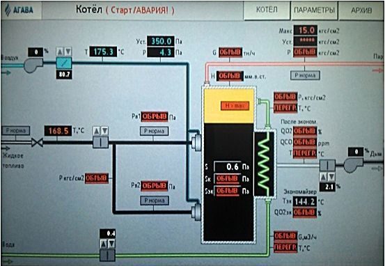
Safety automation of processes for DE-type steam boilers (DE-4-14GM, DE-10-24GM, DE-6.5-14GM, DE-10-14GM, DE-16-14GM, DE-16-24GM, DE-25-14GM, DE-25-24GM), which are designed to generate saturated and superheated steam, we recommend to build on the basis of a microprocessor device (controller) AGAVA 6432.
The AGAVA 6432 controller, when operating on gas or liquid fuel, in accordance with the operating manual for the boiler, federal norms and rules in the field of industrial safety, technical regulations of the Russian Federation and the Customs Union in the field of safety, provides: 1) automatic check of the tightness of gas valves, 2) automatic ignition of the gas boiler burner, 3) semi-automatic or manual ignition of the oil burner, 4) post-emergency ventilation of the furnace for at least 10 minutes.
The safety shutdown of the burner occurs when one of the events is detected: 1) increase / decrease in gas pressure in front of the burner; 2) lowering the pressure of the liquid fuel in front of the burner; 3) lowering the air pressure in front of the burner; 4) lowering the vacuum in the furnace; 5) an increase in the level in the boiler drum above the upper emergency level; 6) lowering the level in the boiler drum below the lower emergency level; 7) increasing the steam pressure in the boiler drum;  extinguishing of the torch of the burner or igniter; 9) turning off the smoke exhauster; 10) turning off the blower fan; 11) cessation of power supply or loss of voltage on remote and automatic control devices and measuring instruments.
In addition to the implementation of all mandatory protections, the automation, based on the AGAVA 6432 microprocessor device (controller), performs: 1) automatic smooth regulation of the boiler power according to the steam pressure in the boiler drum or the gas pressure on the boiler; 2) automatic smooth regulation of the fuel / air ratio by controlling the actuator of the fan guide vanes or the variable frequency drive of the fan motor; 3) automatic smooth regulation of the vacuum in the boiler furnace by controlling the actuators of the exhaust fan guide or the frequency-controlled drive of the exhaust fan motor; 4) automatic smooth regulation of the water level in the boiler drum by controlling the actuator of the control valve on the water supply to the boiler; 5) correction of the table of the fuel / air ratio by the oxygen content in the exhaust gases or by the temperature of the air entering the burner; 6) control and protection of the boiler when operating on reserve liquid fuel.
To register events and the main technological parameters of the boiler, an electronic recorder is implemented in the controller.
It is advisable to build an automation system for a hot water boiler of the KVGM type on the basis of the KR-300ISh controller with an "upper level" control.
At the same time, the automation system uses a personal computer and the TRACE MODE 5.0 SCADA system for display and control.
Let us consider the main elements of the automation set based on the KR-300ISh controller, which make it possible to effectively control the KVGM type boiler. They are:
1) ShchUK program control panel, in which are installed:
multifunctional microprocessor controller KR-300ISH KGZHT.421457.001, consisting of:
a) controller block BK-Sh-1-1-XXX-20-1.5-1 with terminal block connectors KBS-72Sh;
b) block BUSO-Sh-XXXX-0-1.5 with terminal block connectors KBS-96SH-1.5;
c) power supply units of the BP-Sh-1-9 and BP-4M controller;
2TRM1 temperature and pressure meters;
2) a board of executive devices, in which are installed:
automatic switches, switching and protective equipment;
non-contact reversible starters PBR-2M;
power supplies Karat-22, BP-10, BUS-30;
3) software "LEONA";
4) software "TRACE MODE";
5) pressure transducers with electrical output of the Metran-100, TSM-0193, TSP-0193 type and actuators of the MEOF-100 / 25–0.25u-99 type;
6) ignition-protective device ZZU-4;
7) selective devices for impulses of air pressure, vacuum in the furnace, water pressure, as well as electromagnetic flow meters for measuring the flow of water from the boiler.
Thus, using modern automation systems for the operation of steam boilers, we control all the factors of the technological process. This happens through the measurement of the main parameters of the operation of the boiler units and the timely signaling of failures in the boiler system. Thus, we ensure long-term and trouble-free functioning of boiler houses, as well as increase the safety of technical personnel.
Literature:
- Federal norms and rules in the field of industrial safety "Industrial safety rules for hazardous production facilities where equipment operating under excessive pressure is used" (Rostekhnadzor order No. 116 of March 25, 2014).
- SP 62.13330.2011 * Gas distribution systems. Updated edition of SNiP 42-01-2002 (with Amendment No. 1)
- SP 89.13330.2012 Boiler plants. Updated edition of SNiP II-35–76. SP (Code of Rules) dated June 30, 2012 No. 89.13330.2012
- GOST R 54961–2012 Gas distribution systems. Gas consumption networks. General requirements for operation. Operational documentation. GOST R of August 22, 2012 No. 54961–2012
- GOST 21204–97 Industrial gas burners. General technical requirements (with Amendments N 1, 2). GOST dated April 25, 1997 No. 21204-97
Automation object
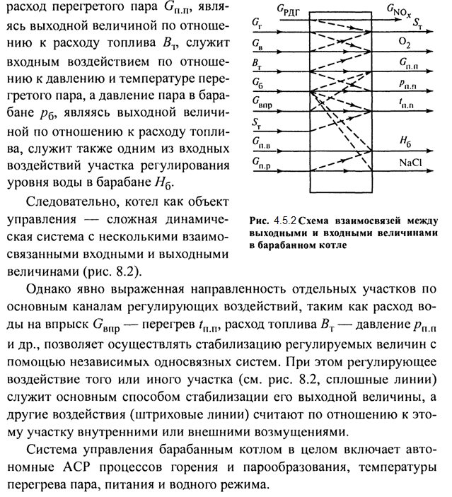
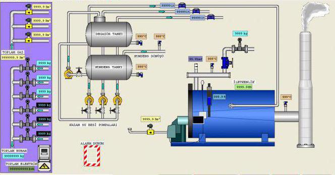
Boiler equipment as an object of regulation is a complex dynamic system with many interconnected input and output parameters. The automation of boiler houses is complicated by the fact that the rates of technological processes are very high in steam units. The main regulated values include:
- flow rate and pressure of the heat carrier (water or steam);
- discharge in the firebox;
- the level in the feed tank;
- In recent years, increased environmental requirements have been imposed on the quality of the prepared fuel mixture and, as a consequence, on the temperature and composition of the flue gas products.
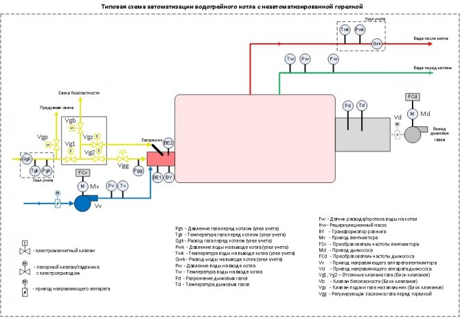
AUTOMATIC REGULATION OF STEAM BOILERS
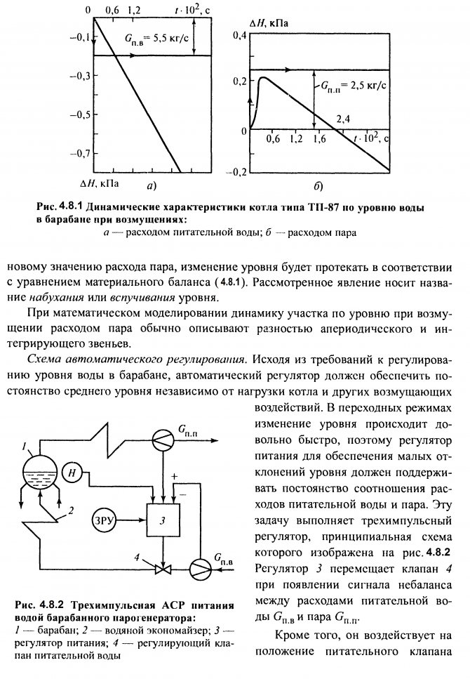
4.5 Drum steam boiler as a control object
A schematic diagram of the technological process taking place in a drum steam boiler is shown in Fig. 4.5.1. The fuel enters through the burners into the furnace 7, where it is usually burned by a flare method. To maintain the combustion process, air is supplied to the furnace in an amount QB.
It is pumped using a DV fan and preheated in an air heater
9.
Flue gases formed during combustion Qg
sucked from the furnace with a DS smoke exhauster. Along the way, they pass through the heating surfaces of superheaters 5,
6
, water economizer
8
, air heater
9
and are discharged through the chimney into the atmosphere.
The vaporization process takes place in the riser pipes of the circulation circuit 2, shielding the chamber furnace and supplied with water from the downpipes 3.
Saturated steam Gb from drum
4
enters the superheater, where it is heated to the set temperature due to radiation from the torch and convective heating with flue gases. In this case, the superheat temperature of the steam is controlled in the desuperheater 7 by means of water injection Gvpr.
The main controllable values of the boiler are the superheated steam flow rate Gp.p
, his pressure
Pp.p
and temperature t
p.p
... The steam flow rate is variable, and its pressure and temperature are kept close to constant values within the permissible deviations, which is due to the requirements of a given operating mode of a turbine or other consumer of thermal energy.
In addition, the following values should be maintained within acceptable tolerances:
water level in the drum Hb
- regulate by changing the feed water supply
GP.B
;
vacuum in the upper part of the firebox ST
- regulate by changing the supply of smoke exhausters sucking flue gases from the furnace;

Fig. 4.5.1. Basic technological scheme of a drum boiler:
GPZ - main steam valve; RPK - regulating feed valve; 1
- firebox;
2
- circulation circuit;
3
- drop coarse;
4
- drum;
5,6
- steam superheaters; 7 - desuperheater;
8
- economizer;
9
- air heater
4.6 Regulation of combustion and vaporization processes
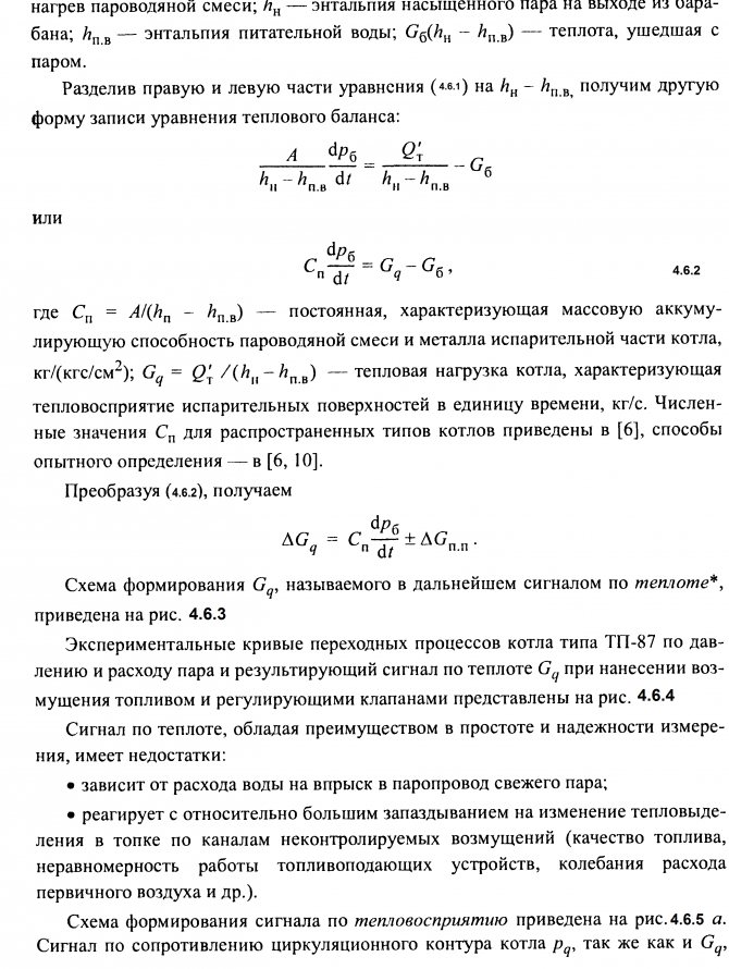
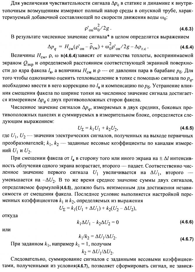
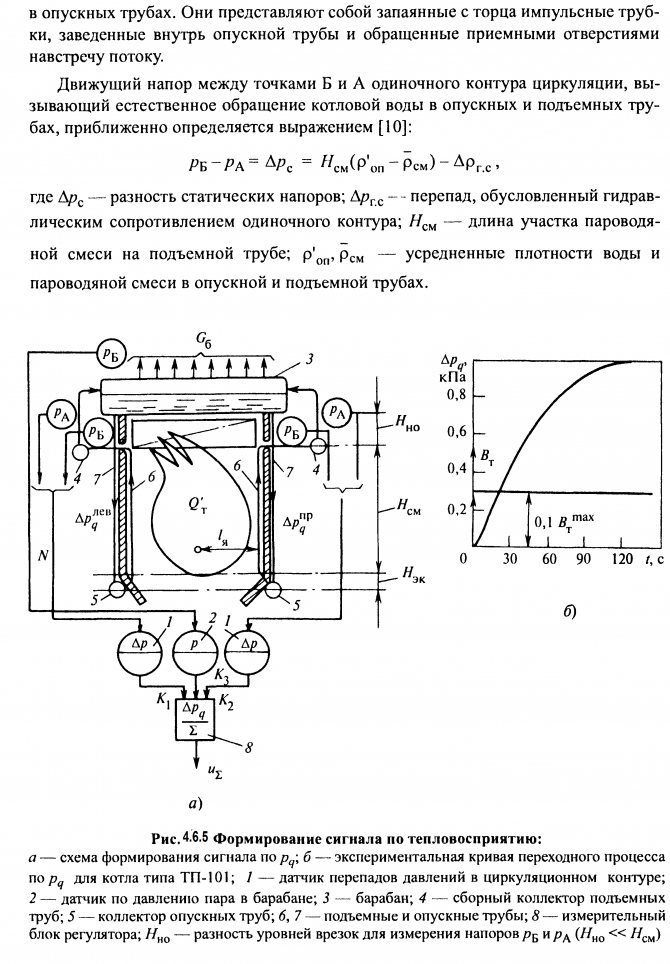
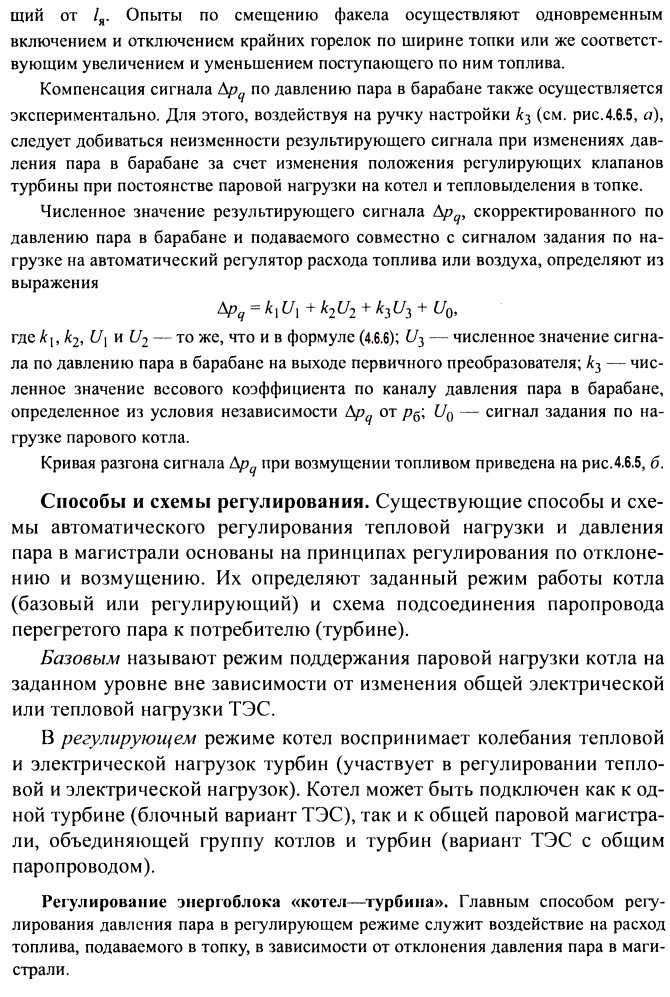
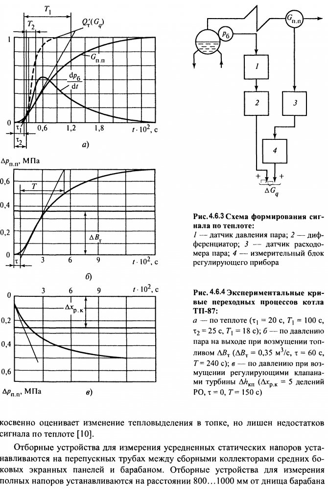
Fig. 4.6.5 Control circuit diagram
steam pressure in front of the turbine:
1 - fuel supply regulator; 2 - regulator of rotation frequency (speed); 3 - turbine control valves; 4 - pressure regulator; 5 - electric drive of the turbine synchronizer
A schematic diagram of a closed ACP of steam pressure in front of the turbine for the case under consideration is shown in Fig. 4.6.5, line but.
In this diagram, the steam pressure is maintained by the pressure regulator
4
acting on the fuel supply regulator U, and the turbine rotor speed - the speed regulator
2.
In the basic mode, the effect of the pressure regulator should be switched to the control mechanism of the control valves of the turbine 3 through the electric drive of the synchronizer of the turbine 5 (Fig. 4.6.5 - line b).
Regulation of a group of boilers with a common steam line. A schematic diagram of regulation for this case (diagram with a main regulator) is shown in Fig. 4.6.7, a. Maintaining the steam pressure in the common line close to a constant value in the steady state ensures the supply of a given amount of fuel to the furnace of each boiler. In a transient mode caused by a change in the total steam load, the steam pressure is regulated by supplying fuel to each boiler or part of them. In this case, there can be two cases.
All boilers operate in a regulating mode. The deviation of the steam pressure in the common steam line pm will lead to the appearance of a corresponding signal at the input of the main regulator 3. It controls the fuel supply regulators of all boilers. The share of each of them in the total steam load is set using manual control dials (ZRU).
Some of the units are transferred to the basic mode by disconnecting the connections of the fuel supply regulators with the main regulator. The steam pressure in the common steam line is controlled by units, the connections of which with the main regulator are not broken. This solution is advisable with a large number of boilers operating in parallel, when there is no need to keep all units in a regulating mode.
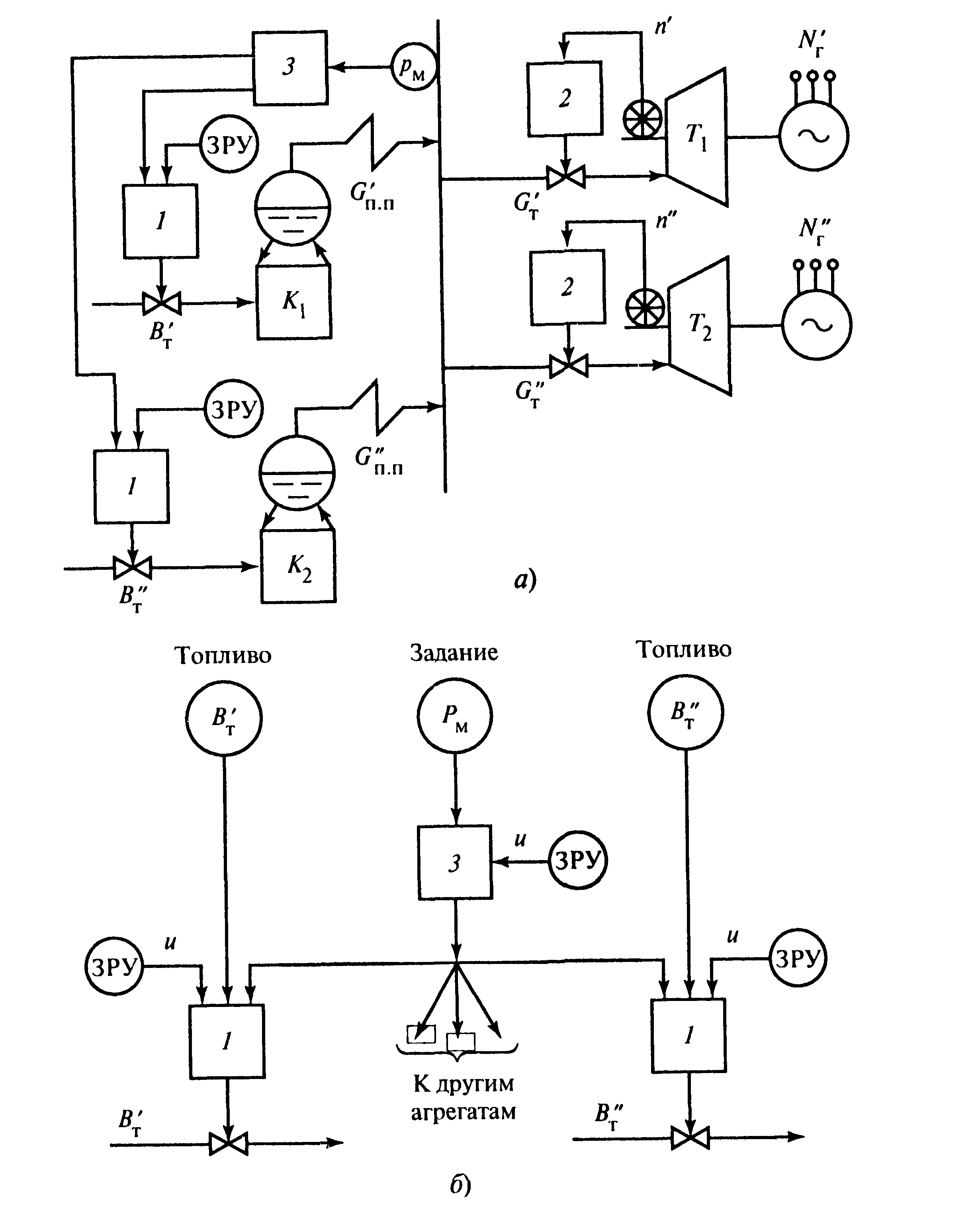
Fig. 4.6.7. Schematic diagrams of steam pressure regulation in a common steam line with a main regulator (a) and stabilization of fuel consumption (b):
1 - fuel supply regulator; 2 - turbine speed regulator; 3 - main steam pressure regulator; K1, K2 - boilers; Т1, Т2 - turbines
In the first case, uniform distribution of loads from the steam consumer between individual units is ensured, in the second - the stability of the steam load of units operating in the basic mode.
Let's follow the operation of the ACP with the main regulator in case of intra-furnace disturbances. Let us assume that the disturbance arrives through the fuel supply channel.
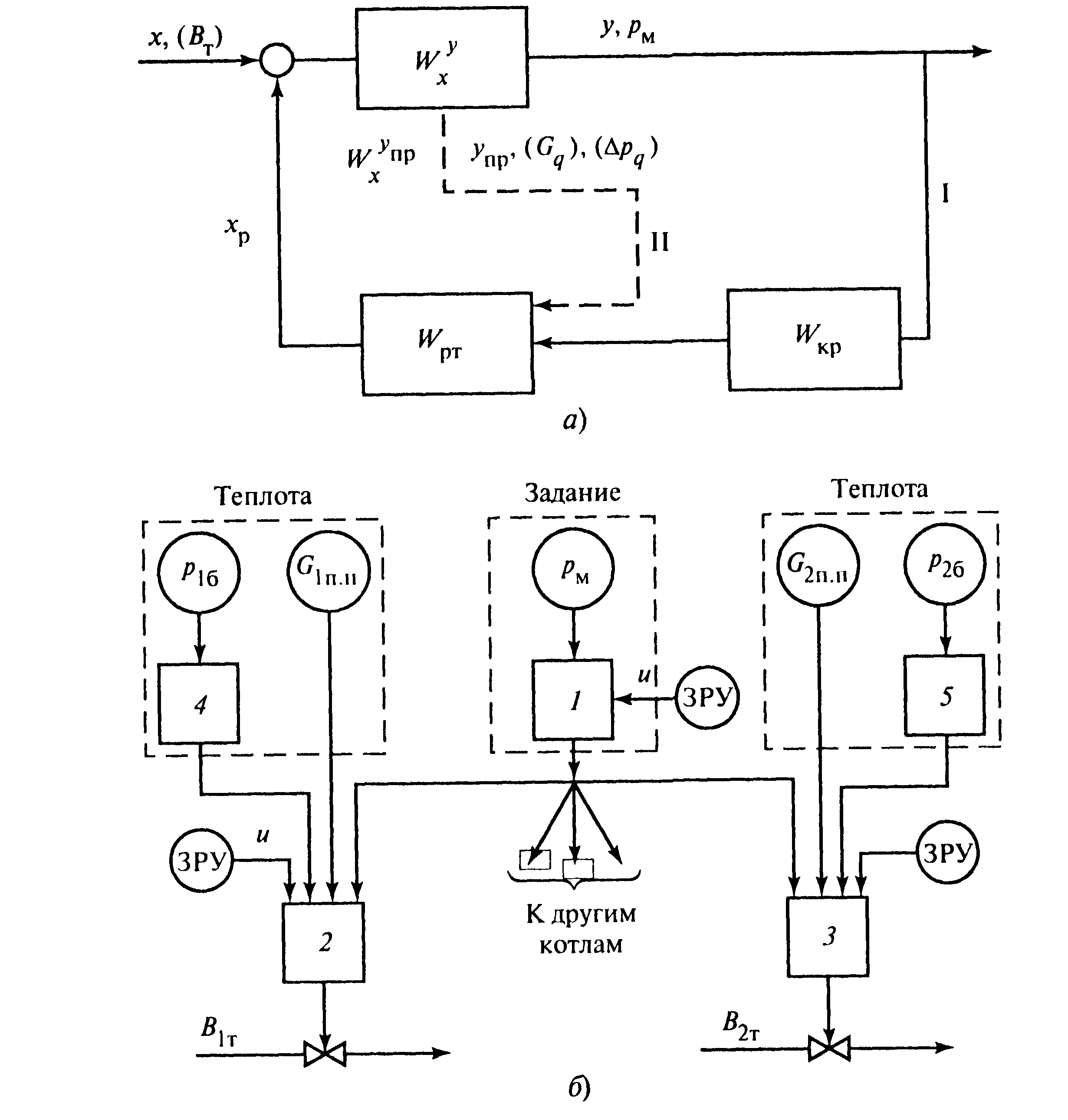
Fig. 4.6.8 Regulation of the fuel supply according to the "reference-heat" scheme:
a, b - structural and functional diagrams; I, II - external and internal contours; 1 - steam pressure regulator; 2, 3 - fuel regulators; 4.5 - differentiators
Even less inertia in comparison with the heat signal is possessed by the signal on the heat perception of the furnace walls ∆pq. Its use in the ACR of a heat load instead of a heat signal makes it possible to improve the quality of regulation due to an increase in the speed of the stabilizing circuit II (see Fig. 8.8, a).
Regulation of the efficiency of the combustion process. The efficiency of the boiler is assessed by the efficiency, which is equal to the ratio of the useful heat spent on generating and superheating steam to the available heat that could be obtained by burning all the fuel.

Curves of the transient process of the section for the oxygen content 02 in the flue gases behind the superheater when disturbed by an increase in the air flow ∆Qw, the guide vanes (HA) of the blowing fans as a percentage of the position indicator (% UP) and gas fuel ∆BT
m3 / h are shown in Fig. 4.6.9, b. The inertia of the section depends on the volume of the combustion chamber and the adjoining gas duct, as well as on the delay in the measuring device. In the mathematical description of the dynamic properties, this section is represented as a sequential connection of two links: transport delay τ and inertial first order with a time constant T [26].
Methods and schemes of regulation. The main way to regulate the excess air behind the superheater is to change its amount supplied to the furnace using blowing fans. There are several options for automatic air supply control schemes, depending on the methods for indirectly assessing the efficiency of the combustion process by the ratio of various signals.
1. Regulation of efficiency according to the fuel-air ratio. With a constant fuel quality, its consumption and the amount of air required to ensure the required combustion efficiency are linked by a direct proportional relationship established as a result of operating tests. If the measurement of fuel consumption is performed accurately enough, then the maintenance of an optimal excess of air can be realized using a control scheme known as fuel-air (Fig. 4.6.10, a). With gaseous fuel, the required ratio between the amounts of gas and air is carried out by comparing the pressure drops across the restriction devices installed on the gas pipeline and on the air heater RVP or on a special measuring device for the air flow rate. The difference of these signals is fed to the input of the automatic economy regulator, which controls the supply of the blowing fans.
Continuous measurement of solid fuel consumption, as already noted, is an unsolved problem. Sometimes the consumption of pulverized fuel is estimated, for example, by the position of the regulating body (crosshead of the flat controller), which determines only the frequency of rotation of the feeders, but not the consumption of dust. This control method does not take into account the qualitative change in the composition and fuel consumption associated with an increase or decrease in the speed of the transporting air or with a disruption in the normal operation of the dust feeders. Therefore, the use of the fuel - air scheme is justified only in the presence of liquid or gaseous fuel of constant composition.
2. Regulation of efficiency according to the steam - air ratio. A different amount of air is required per unit of consumption of a fuel of different composition. The same amount is required per unit of heat released during the combustion of different types of fuels. Therefore, if we evaluate the heat release in the furnace by the steam flow rate and change the air supply in accordance with changes in this flow rate, then, in principle, an optimal excess of air can be achieved.
3. This principle of air supply regulation is used in the steam-air scheme (Fig. 6.6.10, b).
Regulation of efficiency according to the ratio of heat-air signals (Figure 6.6.10, c). If the heat release in the furnace Qt 'is estimated from the consumption of superheated steam and the rate of change in the steam pressure in the drum, then the inertia of this total signal (Gq, see Fig. 6.6.4, a) under furnace disturbances will be significantly less than the inertia of one signal in terms of the steam consumption Q n n
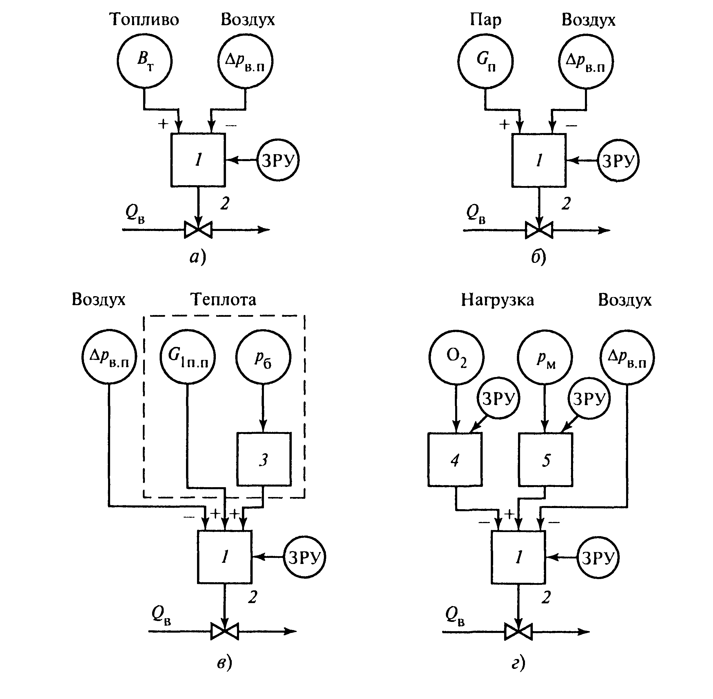
Fig. 4.6.10. Air supply regulation according to the ratio:
a - fuel - air; b - steam - air; c - heat - air; d - load - air with O2 correction; 1 - air supply regulator; 2 - regulatory body; 3 - differentiator; 4 - corrective air regulator; 5 - overheated steam pressure correcting regulator (load reference regulator)
The amount of air corresponding to a given heat release is measured by the pressure drop across the air heater or by the air pressure in the fan discharge pipe. The difference between these signals is used as an input to the economy controller.
four.Efficiency control according to the reference - air ratio with an additional signal for the O2 content in the flue gases (Fig. 4.6.10, d). O2 content in fuel combustion products characterizes excess air and weakly depends on the fuel composition. Therefore, the use of O2 as an input signal to an automatic regulator affecting the air flow rate is quite reasonable. However, the implementation of this method is difficult due to the lack of reliable and fast-acting oxygen gas analyzers. Therefore, in industrial conditions, air supply control schemes have become widespread not with direct, but with corrective action for O2.
5.
Maintaining excess air in terms of heat-to-air and especially steam-to-air ratios is simple and reliable, but not accurate. For example, the economy control system, operating according to the task - air scheme with additional O2 correction, is devoid of this drawback. The system as a whole combines the principles of disturbance and deflection control. The air supply regulator I changes its flow rate according to a signal from the main or corrective pressure regulator 5, which is an automatic regulator set by the boiler load. The signal proportional to the air flow rate rvp acts as in other circuits:
firstly, it removes disturbances in the air flow rate that are not related to the regulation of efficiency (turning on or off dust preparation systems, etc.);
secondly, it helps to stabilize the process of regulating the air supply itself, since it simultaneously serves as a signal of hard negative feedback.
The introduction of an additional correction signal for the O2 content increases the accuracy of maintaining the optimal excess air in any efficiency control system. Additional corrective regulator 4 for O2 in the setting - air regulation scheme controls the air supply in case of furnace disturbances and directly maintains the specified excess air in the furnace.
Regulation of vacuum in the furnace. The presence of a small (up to 20 ... 30 Pa) constant vacuum ST in the upper part of the furnace is necessary under the conditions of the normal combustion mode. This prevents gases from being knocked out of the furnace, contributes to the stability of the torch and serves as an indirect indicator of the material balance between the air supplied to the furnace and the exhaust gases. The rarefaction control object is a combustion chamber with gas ducts connected in series with it from the reversing chamber to the suction pipes of the smoke exhausters. The input regulating effect of this section is the flue gas flow rate, which is determined by the supply of smoke exhausters. External disturbing influences include a change in the air flow rate depending on the heat load of the unit, internal disturbances - violations of the gas-air regime associated with the operation of dust preparation systems, slag removal operations, etc.
The curve of the signal change for the rarefaction of the upper part of the furnace ST, with disturbance by the flow rate of flue gases, is given in [26]. The rarefaction section has no lag, has low inertia and significant self-leveling. The negative property of the site is the fluctuations of the regulated value around the average value of St 'with an amplitude of up to 30 ... 50 Pa (3 ... 5 mm of water column) and a frequency of up to several hertz.
Such fluctuations (pulsations) depend on a large number of factors, in particular on the pulsations of fuel and air consumption. They complicate the operation of control devices, especially those with relay amplifying elements, causing them to operate too often.
To smooth out pulsations, special damping devices are installed in front of the primary measuring devices: throttling tubes and washers, impulse pipes of increased diameter or intermediate cylinders (tanks).For this, an electrical damper is also used, which is available in the electrical circuits of the measuring units of regulating devices [21].
Methods and schemes of regulation. The regulation of the vacuum is usually carried out by changing the amount of exhaust gases sucked out by the smoke exhausters. Moreover, their supply can be regulated:
• rotary multi-axis butterfly valves (see Fig. A.2, e);
• guide vanes (see Fig. A.7);
• hydraulic couplings, changing the number of revolutions of the impeller of the smoke exhauster (see Fig. A.6), or by the prime mover, changing the speed.
Comparison of various control methods in terms of specific consumption of electrical energy for the drive of smoke exhausters is shown in Fig. A.8.
Fig. 4.6.11. ACP vacuum in the furnace
The most widespread is the rarefaction control circuit with a single-pulse PI controller, which implements the principle of control by deviation (Fig. 4.6.11).
The required value of the controlled variable is set using the manual setpoint switchgear of the vacuum regulator 1. When the boiler is operating in the regulating mode, there are frequent changes in the heat load and, therefore, changes in the air flow rate. The operation of the air regulator 2 leads to a temporary disruption of the material balance between the incoming air and the flue gases. To prevent this violation and increase the speed of the vacuum regulator, it is recommended to introduce at its input an additional disappearing effect from the air regulator through a dynamic coupling device 3.
As a dynamic communication device, an aperiodic link is used, the output signal of which is fed to the input of the vacuum regulator only at the moments of movement of the actuator of the air regulator.
Primary air pressure regulation. The velocities of the dust-air mixture in the dust lines to the burners for boilers with an industrial bunker should vary only within certain limits, regardless of the steam load and the total air flow rate. This limitation must be observed due to the danger of clogging of the dust pipes and due to the conditions for maintaining the proper velocities of the primary air at the mouth of the burners.
The regulation of the primary air supply to the dust pipes is carried out using a regulator that receives a signal from the air pressure in the primary air duct and acts on the primary air fan supply or on the throttle valves installed on the common air inlets to the primary air duct.
The transient process curve for the primary air pressure in the common box is given in [26].
4.6.1 Regulation of superheat of steam drum boilers
The superheating temperature of steam at the boiler outlet is one of the most important parameters that determine the efficiency and reliability of the steam turbine and the power unit as a whole. In accordance with the requirements of PTE, permissible long-term deviations of the overheating temperature
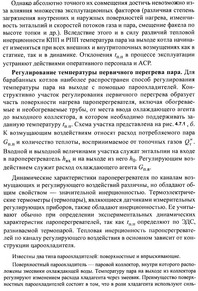

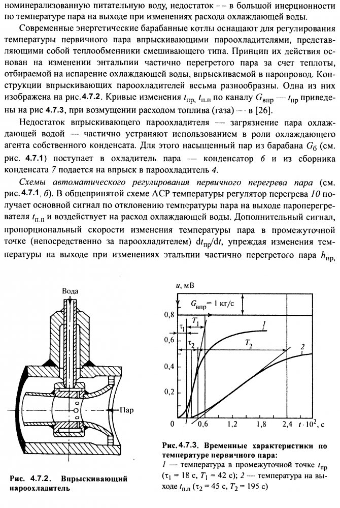
disappears in steady state. For the formation of the disappearing signal, a real differentiating link is usually used.
The approach of the injection point to the outlet of the superheater reduces the inertia of the section and, therefore, improves the quality of control processes. At the same time, this leads to a deterioration in the temperature regime of the metal of the heating surfaces located before the desuperheater. Therefore, on powerful power boilers with advanced superheaters, multistage control is used. For this purpose, two or more injection devices are installed along the steam flow, controlled by automatic temperature regulators.
This makes it possible to more accurately regulate the temperature of the steam at the outlet of the boiler and at the same time protect the metal of the upstream stages of the superheater.
The automatic regulator at the outlet of each stage also operates according to a two-pulse scheme: with the main signal for the deviation of the steam temperature at the outlet and an additional disappearing signal for the steam temperature after the desuperheater.In the presence of several streams of steam, the primary superheat temperature is controlled separately. The installation of automatic regulators is provided on each of the steam lines.
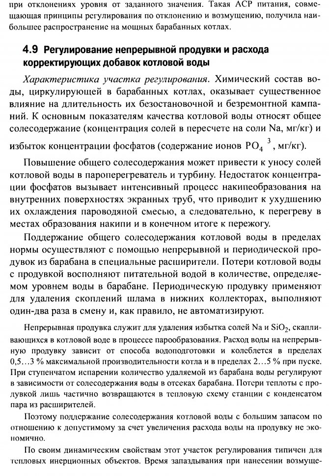
4.8 Regulation of the power supply of steam boilers
It is assumed that the maximum permissible deviations of the water level in the drum are ± 100 mm from the average value set by the manufacturer. The average value of the level may not coincide with the geometric axis of the drum. The maximum permissible deviations are specified during operation. A decrease in the level beyond the limits of the gauge glass installed on the drum is considered a “waste” of water, and an excess of its upper visible part is considered a “overflow”. The distance between these critical marks is 400 mm.
Lowering the level to the point of connection of the standpipes of the circulation circuit can lead to a disruption in the supply and water cooling of the riser pipes. The consequence of this may be a violation of the strength of the pipes at the joints with the drum body, and in the most severe case - burnout. An excessive increase in the level can lead to a decrease in the efficiency of the in-drum separation devices and premature drift of salts in the superheater. Re-feeding the drum and throwing water particles into the turbine cause severe mechanical damage to its rotor and blades. The drum is supplied with water one and, less frequently, two strings of feed water pipelines, one of which serves as a backup.

Automation levels
The degree of automation is set when designing a boiler room or when overhauling / replacing equipment. It can range from manual control based on instrumentation readings to fully automatic control based on weather-dependent algorithms. The level of automation is primarily determined by the purpose, power and functional features of the equipment operation.
Modern automation of the boiler house operation implies an integrated approach - the control and regulation subsystems of individual technological processes are combined into a single network with functional group control.
Automation of steam boilers DKVR with energy saving system "Fakel-2010"
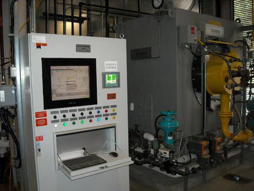
| Instrumentation control cabinet | Engine VFD Control Station | Flue gas analyzer KAKG, IAKG |
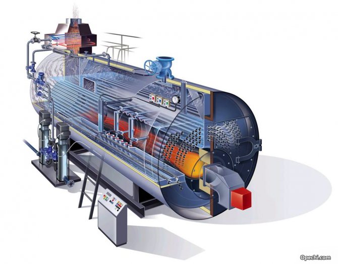
Brief description of DKVr steam boilers Nomenclature of DKVr steam boilers: DKVr-2.5-13; DKVr-4-13; DKVr-4-13-250; DKVr-6.5-13; DKVr-6.5-23; DKVr-6.5-13-250; DKVr-6.5-23-370; DKVr-10-13; DKVr-10-23; DKVr-10-13-250; DKVr-10-23-250 (370); DKVr-10-39; DKVr-10-39-440; DKVr-20-13; DKVr-20-23; DKVr-20-13-250; DKVr-20-23-370. Steam boilers DKVr (E) are designed to generate saturated and superheated steam used for heating and industrial boilers and power plants. The industry produces oil-gas boilers of the DKVr type with a steam capacity of 2.5; four; 6.5; 10 and 20 t / h with a working pressure of 1.3 and 2.3 MPa (13 and 23 kg / cm2). The boilers are equipped with HMG burners, the capacity of the installed burners is determined by the boiler output. On boilers with a capacity of up to 10 t / h, two burners are installed at the front of the boiler in one tier, and on boilers DKVr-20 - three burners in two tiers. An economizer is installed on the boilers to recover the heat of waste gases. To supply air to the burners, the boiler is equipped with a fan of the required capacity. To remove flue gases and create the necessary vacuum in the furnace, the boilers are also equipped with a smoke exhauster of the required performance. The boiler output is regulated by adjusting the output of the burners.
Energy-saving automation for boilers DKVr "from NPF" Uran-SPb " JSC NPF "Uran-SPb" performs a set of works on technical re-equipment of automation and gas supply of the boiler on a turnkey basis ("Scope of services») From the development of design documentation to the installation of equipment and operational adjustment based on the equipment of KB AGAVA. NPF "Uran-SPb" is a dealer of this company, uses devices in its developments and supplies them at manufacturer's prices. During the reconstruction of the automation of steam boilers DKVr, the author's technology of economical and environmentally friendly combustion of fuel "Fakel" is used in the form of an energy saving system "Fakel-2010"... Automatic control of the boiler is provided: with automatic ignition of the burners, with correction of the air supply for combustion according to the analysis of flue gases and frequency control of the speed of rotation of electric motors (VFD). Boiler room operators can interfere with the operation of the automation by transferring it from the “Automatic” mode to the “Manual” mode. The boiler safety automation and control system is based on the AGAVA 6432 microprocessor control device for boilers, ovens, dryers (controller). AGAVA 6432 controller when operating on gas or liquid fuel in accordance with the boiler operation manual, federal rules and regulations in the field of industrial safety, technical regulations of the Russian Federation and the CU in the field of safety, SP 62.13330.2011, SP 89.13330.2012, GOST R 54961-2012, GOST 21204-97 provides:
- automatic check of the tightness of gas valves,
- automatic ignition of the gas boiler burner,
- semi-automatic or manual ignition of oil burners,
- protective shutdown of burners in the event of one of the events: increase / decrease in gas pressure in front of the burner;
- lowering the pressure of the liquid fuel in front of the burner;
- lowering the air pressure in front of the burner;
- lowering the vacuum in the furnace;
- an increase in the level in the boiler drum above the upper emergency level;
- lowering the level in the boiler drum below the lower emergency level;
- increasing the steam pressure in the boiler drum;
- extinguishing of the torch of the burner or igniter;
- turning off the smoke exhauster;
- turning off the blower fan;
- cessation of power supply or loss of voltage on remote and automatic control devices and measuring instruments.
Boiler capacity regulation The AGAVA 6432 controller, in addition to implementing all mandatory protections, performs:
- automatic smooth regulation of the boiler power according to the steam pressure in the boiler drum or the gas pressure on the boiler;
- automatic smooth regulation of the "fuel-air" ratio by controlling the actuator of the fan guide vane or the frequency-controlled drive of the fan motor according to the gas and air pressure,
- vacuum in the boiler furnace by controlling the actuators of the smoke exhauster guide device or the frequency-controlled drive of the smoke exhauster motor by pressure / vacuum in the boiler furnace,
- the water level in the boiler drum by controlling the actuator of the control valve on the water supply to the boiler;
The controller program may provide for the function of reducing the boiler power by switching off (depending on the specific boiler gas supply scheme) one or two burners. To register events and the main technological parameters of the boiler, an electronic recorder is implemented in the controller. An operator's touch panel is additionally installed in the boiler cabinet (by order), into which all analog signals from sensors are displayed for indication in the boiler mimic diagram.
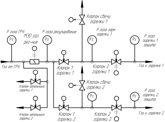
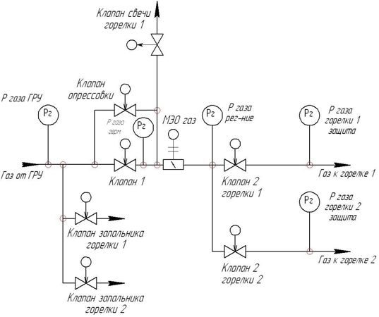
The most common gas supply schemes for 2-burner boilers DKVr
|
|
| Complete gas circuit of a 2-burner boiler, boiler power regulation with a common gas damper. | Complete gas diagram of a 2-burner boiler, boiler output regulation with gas dampers in front of the burners |
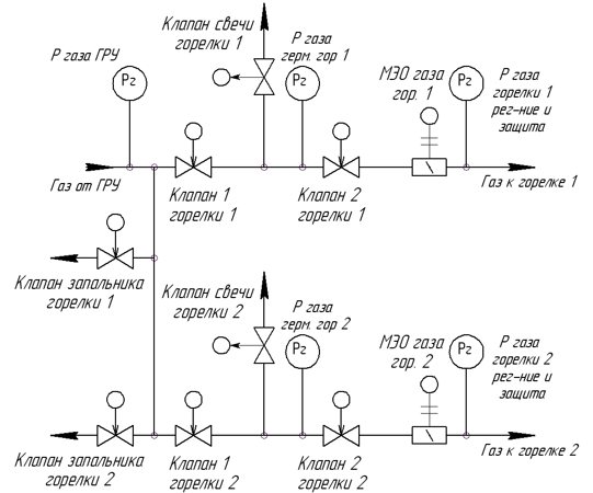
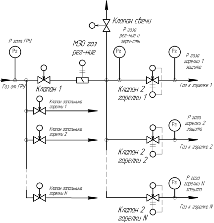
|
|
| Gas circuit of a 2-burner boiler with a common first gas valve along the way, boiler power regulation with a common gas damper. | Gas circuit of a 2-burner boiler with a common first gas valve along the way, boiler power regulation with gas dampers in front of the burners. |

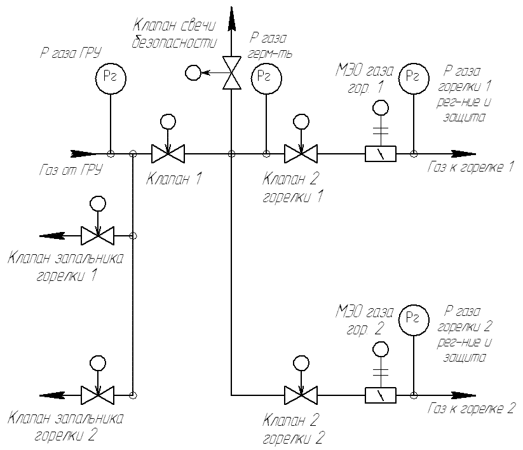
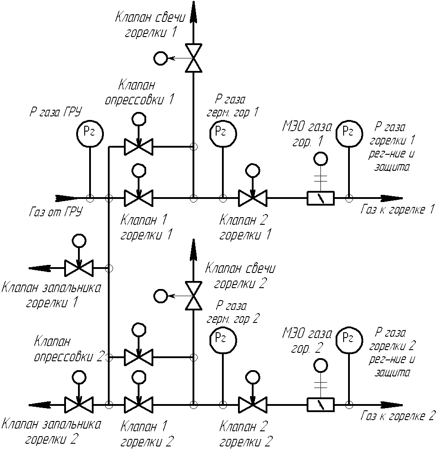
|
|
| Complete gas diagram of a 2-burner boiler with additional pressure testing valves, boiler power regulation with gas dampers in front of the burners. | Gas circuit of a 2-burner boiler with a common first gas valve and an additional pressure test valve, boiler power regulation with a common gas damper. |
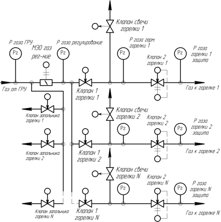
The most common gas supply schemes for 3-burner boilers DKVr-20
|
|
| Complete gas diagram of a 3-burner boiler, boiler power regulation with a common gas damper. | Complete gas diagram of a 3-burner boiler, boiler power regulation with gas dampers in front of the burners. |
The boiler control automation kit includes:
- Instrumentation and control cabinet with installed in it:
- controller AGAVA 6432.20 the composition of the controller may vary depending on the number of required control and monitoring channels,
- indicators ADI-0.1 or multi-range meters of pressure of gas, air, rarefaction ADN, ADR.
- 10-inch operator touch panel for displaying signals from analog and discrete sensors on the boiler mimic diagram and in tabular form, maintaining an archive of analog boiler parameters (installed optionally for 2-burner boilers in accordance with the requirements of the questionnaire and mandatory for 3-burner boilers) ;
- position indicators of actuators ADI-01.7 and toggle switches for remote control of boiler regulators;
- power supplies, surge protection device for powering controller modules and automation devices;
- terminal connectors for connecting external devices.
- Uninterruptible power supply for instrumentation equipment, to protect against short-term voltage dips.
- A set of meters for gas pressure, air, rarefaction type ADN, ADR
- A set of flame detectors ADP for control of the igniter and burner flare.
- Set of pressure sensors for steam and liquid fuel type ADM-100.
- A set of temperature sensors (flue gases, water, etc.).
- Combined flue gas analyzer set: KAKG - to correct the fuel combustion process (installed after the boiler); IACG - to control the efficiency and quality of combustion (installed after the economizer).
- Fuel and water flow meters (supplied if necessary - types of equipment in accordance with the project documentation).
- A set of actuators, gas valves (supplied if necessary - types of equipment in accordance with the project documentation).
- A set of ERMAN frequency converters or AGAVA-E motor control stations for smoke exhauster and fan motors.
ACS TP "Dispatcher" for boiler DKVr Depending on the number of boilers in the boiler room, the dispatch system can be either part of the general dispatch system of the boiler room, or implemented for one boiler. The dispatching system consists of an operator's workstation for a boiler or boiler room, which displays:
- mimic diagram of the boiler, which shows: the state of the boiler actuators, the value of signals from analog sensors, the boiler operating mode;
- graphs of analog values of boiler parameters, current and archived values;
- the event log of the automation operation.
The dispatching system allows the operator to:
- observe the operating modes of the boiler;
- create reports on the operation of the boiler for a certain period with their printout on paper;
- perform remote start / stop of the boiler;
- change the setting for regulating the boiler performance;
- put into remote mode and control the boiler regulators by commands from the PC (option, available upon request).
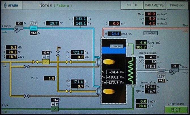
Mnemonic diagram of the boiler on the screen of the control cabinet or the automated process control system "Dispatcher when operating on gas
Mnemonic diagram of the boiler on the screen of the control cabinet or the automated process control system "Dispatcher when operating on liquid fuel
| Boiler operating parameters table on the screen of the "Dispatcher" | Graphs from the archive of boiler parameters on the screen of the "Dispatcher" |
In the computer of the Dispatcher APCS, complete information about the boiler operation is concentrated, both current (instantaneous) and accumulated (memorized):
- on the pressure of steam, gas, liquid fuel, air;
- about rarefaction in the boiler furnace and in the chimney before and after the economizer;
- about the temperature of the outside air, water and flue gases before and after the economizer;
- about the water level in the boiler drum and about the position of the dampers regulating gas, diesel fuel, air, vacuum, water level;
- on the consumption of gas, diesel fuel, steam, feed water and on the consumption of electricity by the smoke exhauster and the fan;
- on the concentration of oxygen and carbon monoxide (underburning) in the exhaust flue gases after the boiler, as well as on the oxygen concentration after the economizer and on the value of the calculated efficiency of the boiler (COP);
- on the state of the discrete (relay) sensors of the object, which act on the warning signaling (light and sound) and on the alarm signaling (to turn off the boiler):
- deviations of gas pressure, level in the boiler drum;
- lowering the vacuum in the firebox, air pressure;
- presence of an igniter and burner torch;
- excess of the permissible steam pressure;
- - lack of ventilation of the furnace;
- loss of voltage in protection circuits;
- emergency shutdown of the boiler.
Delivery set of ACS TP:
- SCADA system,
- APCS software,
- OPC server Agava-OPC,
- RS-485 / USB interface converter,
- Operator's workstation (personal computer, printer) - supplied upon request
Automation supply reference list
During the development and manufacture of boiler automation, the enterprise LLC KB "AGAVA" for the period from 2003 to 2020 delivered automation for 360 boilers (see "Reference list")
The procedure for ordering automation or a full range of works on the technical re-equipment of boilers "DKVr"
JSC NPF Uran-SPb can carry out a full range of turnkey works on the technical re-equipment of automation and gas supply of the boiler from the development of design documentation to the installation of equipment and regime adjustment based on AGAVA equipment.
By agreement with the Customer, only part of the work (design and commissioning) can be performed, but this should not violate the copyright of NPF Uran-SPb on the Fakel system and disclose the secrets of Know-How.
For order:
- a set of automation for the DKVr boiler, a questionnaire is filled in and sent to our address;
- ACS TP "Dispatcher" for the DKVr boiler, the questionnaire is filled in and sent to our address;
- of the project of technical re-equipment of the DKVr boiler, a design assignment or an official letter is sent to us indicating the type of boiler, the number of boilers at the facility subject to technical re-equipment, types of fuel. (It is possible for a specialist to leave for a pre-design survey to draw up a design assignment);
- installation and commissioning, an application is made in any form.
General structure
Boiler house automation is based on a two-level control scheme. The lower (field) level includes devices of local automation based on programmable microcontrollers that implement technical protection and blocking, adjustment and change of parameters, primary converters of physical quantities.This also includes equipment for converting, encoding and transmitting information data.
The upper level can be presented in the form of a graphic terminal built into the control cabinet or an automated operator's workstation based on a personal computer. All information from the low-level microcontrollers and system sensors is displayed here, and operational commands, adjustments and settings are entered. In addition to dispatching the process, the tasks of optimization of modes, diagnostics of technical conditions, analysis of economic indicators, archiving and data storage are solved. If necessary, the information is transferred to the general enterprise management system (MRP / ERP) or settlement.
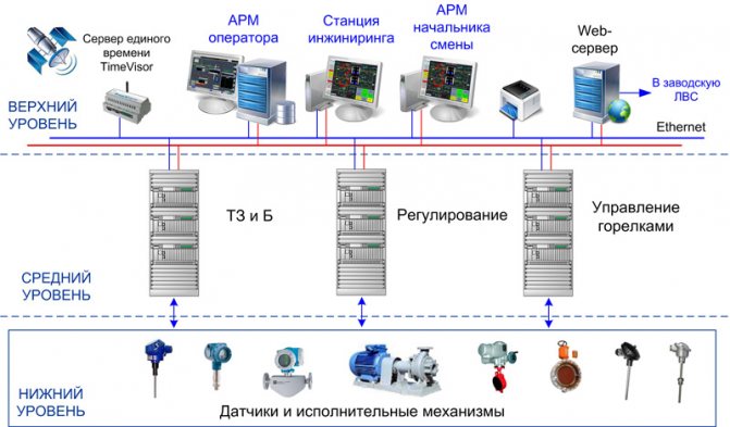
Architecture
Boiler APCS is represented by four hierarchical levels.
The 1st (lower) level includes sensors of measured analog and discrete signals, actuators, including shut-off and control valves, PT30 assemblies.
The 2nd (middle) level includes boiler burner control cabinets.
The 3rd (middle) level of the system includes: microprocessor controllers of technological protection, remote control, automatic regulation and information subsystem.
The 4th (upper) level of the system includes:
- automated workstations of the driver with 100% interchangeability in their functionality (the functions of the operator's station can be combined with the functions of servers)
- an automated workstation for a system engineer - SI, which functionally allows you to perform work to support an automated process control system
- printer for printing event reports, regime sheets, change lists, etc.
Boiler equipment automation
The modern market is widely represented both by individual devices and devices, and by domestic and imported automatic sets for steam and hot water boilers. Automation tools include:
- ignition control equipment and the presence of a flame, starting and controlling the process of fuel combustion in the combustion chamber of the boiler unit;
- specialized sensors (draft gauges, temperature and pressure sensors, gas analyzers, etc.);
- actuators (solenoid valves, relays, servo drives, frequency converters);
- control panels for boilers and general boiler equipment (consoles, sensor mimic diagrams);
- switching cabinets, communication and power supply lines.
When choosing technical means of control and monitoring, the most close attention should be paid to safety automation, which excludes the occurrence of abnormal and emergency situations.
Functions
- Measurement and control of technological parameters
- Detection, signaling and registration of deviations of parameters from the set limits
- Formation and printing of accounting documents
- Archiving the history of parameter changes
- Calculation tasks
- Remote control of technological equipment
- Remote control of actuators
- Execution of technological protection algorithms
- Logic control
- Automatic regulation
- Control of the passage of control commands to the controller
- Maintain the unity of system time
- Differentiation of access to system functions
- Hardware and software self-diagnostics of controllers with information output to board indicators and to the upper level
- Checking the reliability of information signals
- Rapid system reconfiguration and software reconfiguration, etc.
Subsystems and functions
Any boiler room automation scheme includes control, regulation and protection subsystems. Regulation is carried out by maintaining the optimal combustion mode by setting the vacuum in the furnace, the primary air flow rate and the parameters of the coolant (temperature, pressure, flow rate).The control subsystem outputs actual data on the operation of the equipment to the human-machine interface. Protection devices guarantee the prevention of emergency situations in case of violation of normal operating conditions, the supply of a light, sound signal or shutdown of the boiler units with the fixation of the cause (on a graphic display, a mnemonic diagram, a board).
Automation "Kontur-2". The principle of operation of automatic control
|
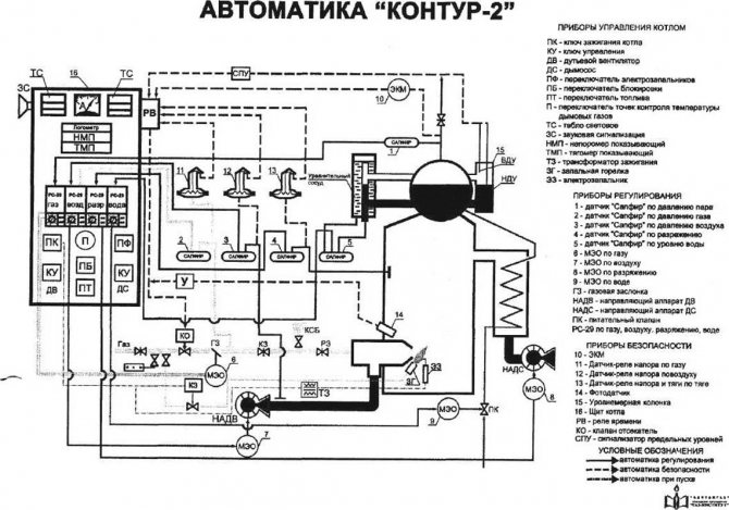
Purpose:
Automation "Kontur-2" is designed to automatically maintain the steam pressure or water temperature (hot water boiler) constant. Installed on steam boilers with a steam pressure over 0.7 kgf / cm2 and hot water boilers with a water heating temperature over 115 ° C.
Manufacturer:
Moscow plant of thermal automation.
The principle of operation of automatic control
The change in steam pressure is sensed by the "Sapphire" sensor, in which the output signal to the RS-29 regulator changes, in which it is processed, amplified and then fed to the MEO, in which the engine is turned on, which moves the gas damper through a system of levers, as a result of which the gas pressure changes. The change in gas pressure is sensed by the "Sapphire" sensor for gas, in which the output signal arriving at the RS-29 regulator through the air changes, and when the signals from the "Sapphire" through the gas and from the "Sapphire" through the air are equal in magnitude, the output signal from the PC -29 on air at MEO stops and the engine stops.
As a result of a change in the load on the burner, the vacuum changes, this is sensed by the "Sapphire" sensor, according to the vacuum in which the output signal changes to the PC-29 regulator, in which it is processed, amplified and fed to the MEO, in which the engine is turned on and through a system of levers moves the guide vanes of the smoke exhauster until the preset vacuum is restored.
As a result of the transformation of water into steam, the water level decreases, this is sensed through the equalizing vessel by the "Sapphire" sensor, according to the water level, the output signal to the RS-29 regulator changes, according to the water level in which it is processed, amplified and then fed to the MEO , in which the engine is turned on and through a system of levers opens the feed valve.
Operating principles of safety automation
The electrical signal from the primary safety device goes to the boiler shield and through the sensor relay the sound and light alarm is turned on, then the signal goes to the time relay, where there is a delay of up to 30 seconds (except for the flame extinguishing), and if the operator, switching to manual control, does not restore parameter, the time relay breaks the circuit, the electric slam-shut device is triggered, the gas supply to the boiler stops.
Boiler start-up with "Kontur" automatics
a) preparation for ignition:
- written order;
- prepare the boiler for ignition;
- check that all shut-off valves on the gas pipeline, except for the valve for the safety plug, are closed;
- check the state of the automation devices by external inspection;
- set the toggle switch on the RS-29 to manual control;
- install the electric igniter switch on the ignited burner;
- set the switch for blocking the smoke exhauster and the fan to the interlocked position;
- set the fuel type switch to "gas";
- supply power to the boiler shield;
- remove the sound signal;
- use more or less toggle switches from RS-29 on gas to check the operation of MEO and open the gas damper to the position according to the instructions for ignition;
- use more or less toggle switches from RS-29 to check the operation of MEO through the air and close the fan guide;
- use the more or less toggle switches from the RS-29 under vacuum to check the operation of the MEO and close the guide vane;
- use more or less toggle switches from RS-29 on water to check the work of MEO;
- turn on the smoke exhauster with the key from the shield and open the guide vane;
- turn on the fan using the key from the panel and open the guiding device (ventilate the firebox according to the time specified in the instructions, and after the ventilation time has expired, set the minimum vacuum and air pressure;
b) boiler firing up:
- open the main valve;
- open the tap in front of the electric igniter valve and use the key from the panel to light it (if there is no electric igniter, light the portable igniter and bring it into the furnace);
- engage the levers of the shut-off valve;
- open the control valve;
- close the tap on the safety plug;
- after making sure that the igniter is on, slowly open the operating valve on the burner, observing the gas ignition and pressure according to the manometer;
- close the tap in front of the electric igniter valve (close the tap on the portable igniter and remove it from the furnace);
- adjust the combustion of the burner;
- write in the journal.
Stopping the boiler
- written order;
- switch the toggle switch on the RS-29 to manual control;
- using toggle switches more or less reduce the burner load to the minimum
- close the working valve;
- close the control valve;
- open the tap on the safety plug;
- close the main valve;
- after the post-stop ventilation time has elapsed, turn off the fan and the smoke exhauster;
- after the vapor pressure drops to zero, turn off the power to the stake shield;
- write in the journal.
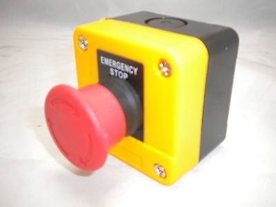
- Emergency stop is made with a key from the shield
Communication protocols
Automation of boiler plants based on microcontrollers minimizes the use of relay switching and control power lines in the functional circuit. An industrial network with a specific interface and data transfer protocol is used to communicate the upper and lower levels of the ACS, transfer information between sensors and controllers, and transmit commands to executive devices. The most widely used standards are Modbus and Profibus. They are compatible with the bulk of equipment used to automate heat supply facilities. They are distinguished by high indicators of the reliability of information transfer, simple and understandable principles of operation.
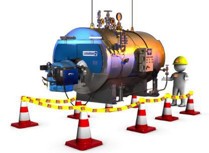
Energy saving and social effects of automation
Automation of boiler houses completely eliminates the possibility of accidents with the destruction of capital structures, the death of service personnel. ACS is able to ensure the normal functioning of equipment around the clock, to minimize the influence of the human factor.
In the light of the continuous growth of prices for fuel resources, the energy-saving effect of automation is of no small importance. Saving natural gas, reaching up to 25% during the heating season, is ensured by:
- optimal ratio "gas / air" in the fuel mixture at all operating modes of the boiler room, correction for the level of oxygen content in combustion products;
- the ability to customize not only boilers, but also gas burners;
- regulation not only by the temperature and pressure of the coolant at the inlet and outlet of the boilers, but also taking into account the environmental parameters (weather-dependent technologies).
In addition, automation allows you to implement an energy-efficient algorithm for heating non-residential premises or buildings that are not used on weekends and holidays.
Automation of steam and hot water boilers: control system "Kontur"
For example, with an increase in gas pressure, which determines an increase in its flow rate, the P.25 regulator issues a command to the actuator to turn on and the actuator moves the blades of the axial guide vane of the blower fan in the direction of increasing the air flow rate.
Furnace vacuum regulator... Depending on the change in the supply of gas and air to the boiler furnace, the vacuum at the top of the furnace will change.
The vacuum sensor is also the DT-2 sensor, which, with a change in the vacuum, sends an electrical signal to the P.25 regulating device, which compares the received signal with the given one and, in the event of their inequality, sends a signal to the impulse mechanism acting on the exhaust fan guide, increasing or decreasing underpressure.
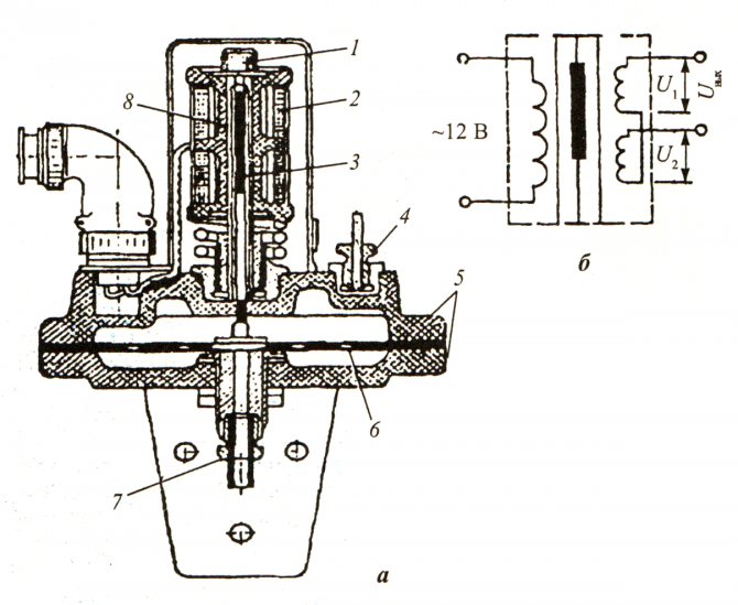
Fig. 131. Differential traction gauge DT-2: traction gauge device; b-electrical circuit; 1 - nut; 2 - the coil of the differential transformer converter; 3 - core of the differential transformer converter; 4, 7 - fitting; 5 - case; 6- membrane; 8 - dividing tube
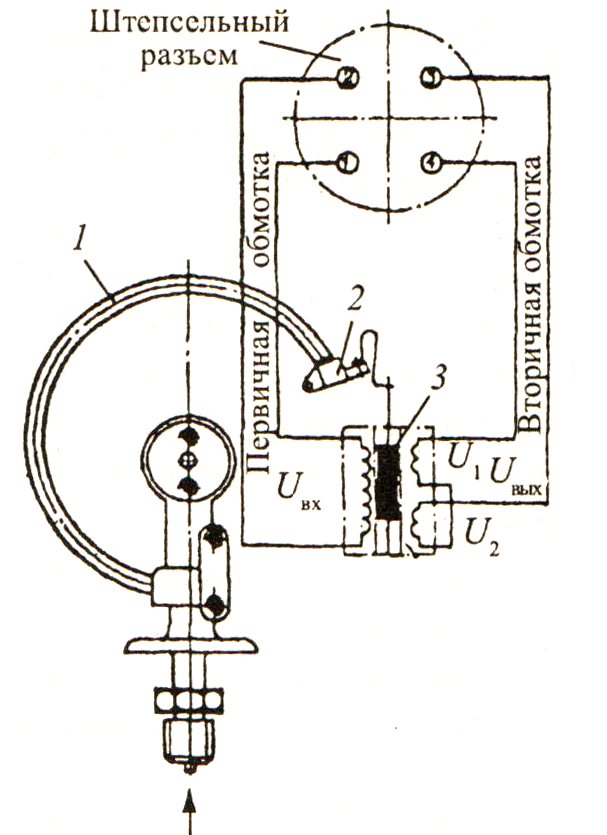
Fig. 130. Remote electric pressure gauge DER: 1 - spring; 2 - free end of the spring; 3 - the core of the differential transformer converter
Water level regulator in the boiler drum. The sensor of this regulator is a differential pressure gauge DM (Fig. 132), which is connected to the boiler drum through a level column. The water pressure drop corresponds to the level in the boiler drum and is fed to the differential pressure gauge. The signal from the differential transformer coil of the pressure gauge is fed to the P.25 regulating device, where it is compared with the preset, set by the setpoint and, in case of inequality of these signals, gives the command to the MI actuator to open or close the PK regulating valve installed on the feed line of the steam boiler.
Hot water boilers are equipped with: water temperature regulator at the boiler outlet; regulator of the ratio "gas-air"; vacuum regulator in the firebox.
The sensors for the regulator of the temperature of the water leaving the boiler are resistance thermometers that measure the temperature of the hot water and the outside air. The sensors convert the temperature into an electrical signal and feed it to the input of the P.25 regulating device, where it is compared with the preset one, and in case of inequality of signals, the P.25 regulating device issues a command to the actuating mechanism of the MI to turn the regulating damper RZ in front of the burners in one direction or another, increasing or by reducing the gas flow. Regulators for the gas-to-air ratio and negative pressure operate in the same way as regulators for steam boilers.
Also, to maintain constant pressure at the inputs to the boiler room, universal flow and pressure regulators URRD can be installed: URRD, URRD-2, URRD-3.
Fig. 132. Differential pressure gauge DM: 1.6 - housing covers; 2,4- membrane boxes; 3 - partition; 5 - nipple; 7 and 15 - impulse tubes; 8 - differential-transformer converter; 9 - cap; 10, 11, 12 - valve; 13 - distribution tube; 14 - rod of the converter core; 16 - zero adjustment bushing; 17 - lock nut