Date of publication: September 13, 2020. Category: Automotive.
An adsorber (often called an absorber) is one of the components of a car that is responsible for absorbing and neutralizing gasoline vapors leaving the tank. Many car owners believe that this is a completely unnecessary device that only creates unnecessary problems, so they often remove it altogether.
However, increased consumption of gasoline and other problems in the operation of the system, as a rule, occur only if the absorber valve fails. Therefore, before ruthlessly removing this node, it will be useful to learn a little more about the features of its operation and the procedure for changing the device.
What is the adsorber used for?
During the operation of the vehicle engine, the gasoline heats up a little, emitting very volatile vapors. Their formation is enhanced by the vibration of a moving car. If the vehicle does not provide for a system for neutralizing harmful vapors, and primitive ventilation is installed, then the formations are simply taken out into the street through special openings.
This picture was observed with almost all old carburetor cars (which is why the car often smelled unpleasantly of gasoline) before the EURO-2 environmental standard, which controls the level of harmful fumes into the atmosphere, appeared. Today, every car must be equipped with an appropriate filtration system to meet the standards. As a rule, the simplest of them is the adsorber.
What is a filter element and how does it work
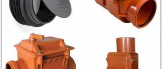
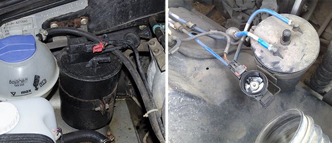
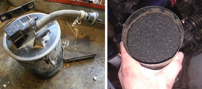
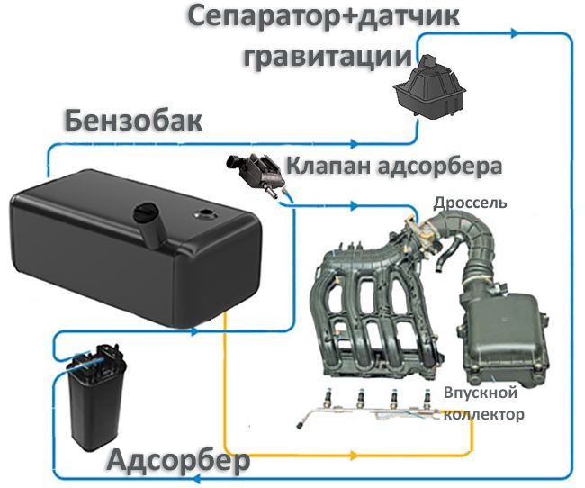
In simple terms, the absorber is a large can filled with activated carbon. In addition, the system contains:
- Separator with gravity valve. It is responsible for trapping fuel particles. The gravity valve, in turn, is used very rarely, but in an emergency (for example, if the car overturned during an accident), it will prevent fuel from overflowing from the gas tank.
- Pressure meter. It is necessary to control the level of gasoline vapors in the tank. As soon as their level is exceeded, harmful components are discharged.
- Filtering part. In fact, this is the very same can with granular activated carbon.
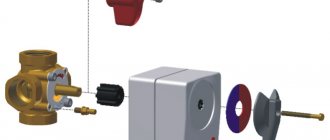
- Solenoid valve. It is used to switch between the modes of capturing the emitted gasoline vapors.
If we talk about the principle of the system, then it is very simple:
- First, gasoline vapors rise in the gas tank and are sent to the separator, where partial condensation of the fuel takes place, which is sent back to the gas tank in liquid form.
- That part of the vapor that could not settle in the form of a liquid passes through the gravitational sensor and is directed to the adsorber.
- When the engine of the car is turned off, gasoline vapors begin to accumulate in the filter element.
- As soon as the engine starts, the canister valve comes into play, which opens and connects the canister to the intake manifold.
- Gasoline vapors combine with oxygen (which enters the system through the throttle assembly) and pass into the intake manifold and engine cylinders, where harmful vapors burn out together with air and fuel.
As a rule, it is the adsorber valve that fails. If it starts to open and close in the wrong mode or completely breaks down, this can negatively affect the operation of the entire car and provoke breakdowns.
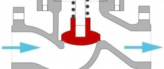
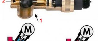
Consider the operation of a poppet valve in a piston or plunger pump (fig. 17).Let the valve disc rise at some speed υ
m. The amount of fluid passing through the opening of the valve seat will be equal to the amount of fluid passing through the gap that forms between the disc and the seat, plus the volume () released by the valve disc when it rises upward.
The area of the slot for an open poppet valve with a flat plate will be:
, (38)
where is the coefficient of compression of the jet in the slotted gap; - the height of the valve disc lift above the seat; d
t is the diameter of the plate.
Based on the above, you can write
, (39)
where is the cross-sectional area of the valve seat opening; - average speed
the growth of fluid in the valve seat; - the velocity of the liquid in the crevice between the disc and the valve seat.
When the valve is lowered, expression (39) will be written as
. (40)
Fig. 17. Diagram of a poppet valve.
If we take the direction of movement of the valve disc upward positive, and downward - negative, then the general expression for raising and lowering the valve disc will be written in the form (Westphal's law):
. (41)
From (41) we determine the height of the valve disc lift:
. (42)
The equation of constancy of the flow rate of fluid moving in the cylinder and in the valve seat bore can be written as:
, (43)
Where v
п is the piston speed ().
Let us write expression (43) taking into account the expression for the piston speed
. (44)
Then equation (42) will take the form:
. (45)
Let's find the speed of the valve disc lift. To do this, we differentiate expression (45) in time:
. (46)
If in expression (46) we discard the term that is small in comparison with, then the expression for the definition takes the form
. (47)
Since the valve disc moves unevenly, the inertia force will act on the disc, which is usually not taken into account in the calculations due to its small value.
The equilibrium equation for the forces acting on the valve disc has the form:
. (48)
where is the gravity of the valve disc in the liquid; R
- the force of compression of the spring; - the pressure difference above and below the valve disc.
Dividing the right and left sides of equation (48) by () we obtain:, (49)
where ∆H
- pressure loss across the valve.
Applying the dependence known from hydraulics to determine the rate of fluid outflow from the hole or nozzle, we determine the rate of fluid outflow from the slotted gap between the valve disc and the valve seat:
, (50)
Where φ
- coefficient of speed of the slotted gap.
The dependence for determining the height of the valve disc lift, taking into account expressions (45), (47) and (50), will take the form:
, (51)
where is the flow coefficient of the valve.
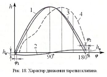
In fig. 18 shows a graphical view of the dependence (51). Sinusoid 1 is constructed using the first term on the right-hand side of equation (51), and cosine 2 is constructed using the second term in the same equation. By summing the ordinates of the sinusoid 1 and cosine 2, a curve 3 was constructed, which expresses the nature of the valve disc movement, that is, the change in its lift height depending on the crank angle. Curve 3 indicates a discrepancy between the valve opening and closing moments with the piston extreme positions. After the crank turns an angle φ
1, the valve disc starts to rise. The crank turned 1800, and the valve is still open and the plate is at a distance
h
0 from the seat surface. After turning the crank at an angle (1800+
φ
2) the valve will close.
Angle φ
1 - valve lag angle when opening, and
φ
2 - valve lag angle when closing.
Lag angles φ
1 and
φ
2 can be determined using the same relationship (51). The valve will open when the crank is turned at an angle
φ
1 determined from the condition that for
φ
=
φ
1
h
= 0.
. (52)
None of the parameters included in the multiplier before the square brackets are equal to zero when the pump is running; only the expression in square brackets can be equal to zero:
= 0, or,
from here
. (53)
We obtain the same dependence for the angle φ
2, but in reality
φ
1 and
φ
2 can be different in size.
For a valve with a flat poppet (see fig. 47) with (but
- width of the supporting surface; - seat bore diameter) S.N. Rozhdestvensky recommends using the following formula to determine the flow rate:
. (54)
However, this formula is suitable only for the quadratic regime of fluid motion through the saddle hole, and this regime takes place at Re
u10.
Here, the Reynolds number of the flow at the entrance to the slot
Re
u =, (55)
where is the hydraulic radius of the slot, determined by the formula:
. (56)
Taking into account dependence (56), expression (55) can be written in the following form:
Re
u =. (57)
For tapered poppet valves with taper angle β
= 450 S. N. Rozhdestvensky recommends the formula
. (58)
This formula is valid for Reynolds numbers 25 <Re
n <300.
For ring valves with a flat disc and narrow seating surface O.V. Baybakov recommends the following formula for determining the flow rate:
, (59)
Where b
- the width of the passage in the valve seat.
Formula (59) is valid for Re
u <10.
The maximum lift of the valve disc will be at φ
= 900, then dependence (51) takes the form
. (60)
Fig. 18 (line 4) shows that h
max takes place when the piston travels a distance greater than, that is, as a result of greater resistance to separation of the disc from the seat, the opening occurs with a jerk. Under the action of the inertial force of the valve disc, its lift occurs at a speed exceeding the speed of the piston in this position. As a result, as the valve plate rises further, its speed will decrease and the lift will be smoother. This is evidenced by the flatter part of the curve.
When the valve is open and liquid flows through it, the hydraulic losses in it are determined by the formula:
, (61)
where is the maximum fluid velocity in the valve seat bore; - coefficient of hydraulic resistance of the valve.
Experiments have shown that hydraulic losses change relatively little with the lift height of the valve disc. A slight decrease occurs during the lowering of the valve disc, that is, when it is not practical to determine the pressure under the valve. Therefore, it is recommended to determine the value for the middle position of the piston, when and h = h
max.
In expression (61), we express the speed in terms of the piston speed v
:
.
Then formula (61) should be written in the form
, (62)
The hydraulic resistance coefficient depends on the valve design.
To determine the coefficient, the following empirical Bach formulas are known:
1. For flat poppet valve with no bottom direction
(63)
Where a
- the width of the contact surface between the disc and the valve seat; - experimental value, which is in the range of 0.15 - 0.16;
d
c is the diameter of the valve seat bore;
h
- the height of the valve disc lift.
The value is recommended to be determined by the formula:
(64)
When using formulas (63) and (64), the following relations between the dimensions must be satisfied h
,
d
with and
a
: 4< <10, 4
a
<
d
s <10
a
.
2. For flat poppet valve with ribbed bottom guides:
; (65)
, (66)
where is a value equal to 1.70 ÷ 1.75; - number of ribs; - rib width; - the width of the contact surface between the disc and the valve seat.
The value of the coefficient is selected depending on the degree of constraint by the ribs of the cross-sectional area of the saddle hole 0.8≤ <1.6; = 0.80 ÷ 0.87, where F
- cross-sectional area of the valve disc ribs;
F
c is the area of the valve seat opening.
3. For poppet valve with tapered seating surface and stem top guide
. (67)
When using the empirical formula (59), the following conditions must be met: 4 <<10; ...
Solenoid valve malfunctions
If the adsorber is in trouble-free mode most of the time, the purge valve can easily stop functioning.This will damage the fuel pump. If the adsorber does not provide proper ventilation, gasoline will gradually accumulate in the intake manifold.
This leads to rather unpleasant "symptoms":
- At idle, so-called dips appear.
- Traction is impaired (it seems that the vehicle is constantly losing power).
- When the engine is running, no operating sound is heard.
- Fuel consumption is noticeably increased.
- There is a hiss and whistle when opening the gas cap.
- The fuel tank sensor literally lives its own life (it can show that the gas tank is full, and after a second - that there is nothing in it).
- An unpleasant gasoline "aroma" appears in the car interior.
Sometimes the filter element, on the contrary, makes too loud sounds, which are also not the norm. To make sure that it is the faulty valve and not the timing belt that is the cause, it is enough to sharply press the gas. If the sound effect remains the same, then most likely the problem is in the adsorber valve.
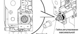
In this case, it is recommended to slightly tighten the adjusting screw of the device. However, you need to twist it no more than half a turn. Locking too tight will result in a controller error. If such manipulations did not help, then you need to conduct a more detailed diagnosis.
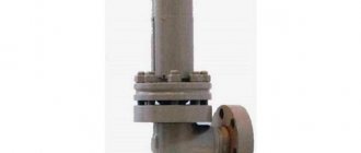
The purpose of the shut-off valve
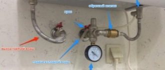
This valve belongs to the shut-off valve and is used to shut off the pipeline in the event of an emergency situation during its operation. The devices can be used not only in industry, but also in everyday life. Most often they are installed in reverse osmosis water purification systems. Here, its role is to protect the receiving container from overflow.
Since an increase in pressure at the outlet of the filter deteriorates the quality of water, a 4-way valve is used to check (control) the operation of the system. If such a situation occurs, the liquid supply line to the filter is closed until the pressure (level) in the tank decreases.
Float cut-off valves are used at gas stations to protect fuel tanks when fuel and lubricants are being drained from a gas station. At nuclear power plants, fast-acting shut-off valves are used in localizing safety systems to protect personnel and the environment from radioactive releases during an accident in a containment. When the parameters characterizing the conditions of normal operation are exceeded, according to the signal from the sensors, the shut-off valves are triggered, sealing the reactor shell.
On the main water pipelines, ball valves with electric one-turn actuators are installed. When the pipe breaks, the speed of water movement increases, which generates a signal to close the shutter. It will take a few seconds to shut off the flow and turn the shut-off element 90 °.
We check the efficiency of the adsorber
To make sure that the malfunction is associated with the valve of this element, you can send the car for a full diagnosis. But, it's expensive, so let's try to identify possible problems on our own.
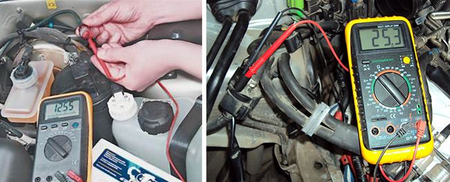
First of all, you need to see if the controller issues errors, for example, "open circuit control". If everything is ok, then use the manual check. To do this, it is enough to prepare a multimeter, a screwdriver and a few wires. After that, you need to follow a few simple steps:
- Raise the hood of the car and find the correct valve.
- Disconnect the wiring harness from this element. To do this, you first need to squeeze out the special lock of the pad fasteners.
- Check if there is voltage to the valve. To do this, you need to turn on the multimeter and switch it to voltmeter mode. After that, the black probe of the device is connected to the car ground, and the red one to the connector marked "A", which is located on the wiring harness. The next step is to start the engine and see what readings the device gives. The voltage should be the same as in the battery.If it does not exist at all, or it is too small, then you may have to look for a more serious problem. If everything is fine with tension, then you can proceed to the next step.
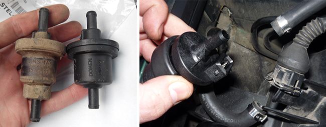
- Remove the purge valve. To remove it, you need to slightly loosen the fastening of the clamps with a screwdriver. After that, it will be possible to easily move the valve slightly upward and smoothly pull it out along the small bracket. After that, the device must be connected directly to the battery terminals. One wire goes to the purge valve (to "+"), and the other is connected to the "minus". After that, both conductors are connected to the corresponding battery terminals. If this does not click, then the valve is completely out of order and it is best to replace it.
We put a new adsorber valve
It is not necessary to contact a car service to replace an element. Work can be done independently with a few Phillips screwdrivers. You also need to purchase a new valve (its marking must completely match the data on the old device).
Thereafter:
- We find the adsorber.
- We remove the negative terminal from the battery.
- Disconnect the wiring block by pressing the latch and pulling the device towards you.
- We loosen the fastenings of the solenoid valve and disconnect the hoses.
- We take out the old device (the bracket will come out with it) from the absorber.
- We install a new device and assemble everything in the reverse order.
Device and mechanism of action
The structure of a poppet check valve is the following set of elements: a disc, a spring, reservoirs, a piston, bypass valves.
The poppet valve has two reservoirs inside its body. One of them is filled with compressed air and the other with air at normal atmospheric pressure. The valve opens together with the release of compressed air from under the piston and closes immediately after the air outlet stops. The characteristic design of the valve ensures its high strength and the ability to function under high pressure. The tightness of the poppet valve is ensured by the specifics of its fastening system. The valve is mounted using flanges sealed with rubber gaskets.