Pros of the Valtec system
Valtec mixing unit specification for underfloor heating
Before starting installation and selecting a mixing unit for a Valtec underfloor heating, it is necessary to analyze the advantages of this type of water circuit.
- Thanks to high-quality materials, durable fasteners, reliable operation is ensured.
- Modularly designed components fit exactly together, eliminating the risk of leaks.
- The manufacturer has provided for the production of related materials required for thermal and waterproofing equipment.
Calculation instructions
In order to correctly develop a project for laying a warm floor, a preliminary calculation of the main indicators will be required, focusing on their average values.
Do-it-yourself installation of a water-heated floor
Various factors have to be taken into account, including the role of the water floor as the main type of heating or its use as an additional source of heat. Since a detailed calculation for self-execution is a complex process, in practice, averaged parameters are used.
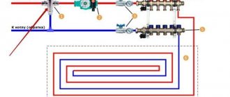
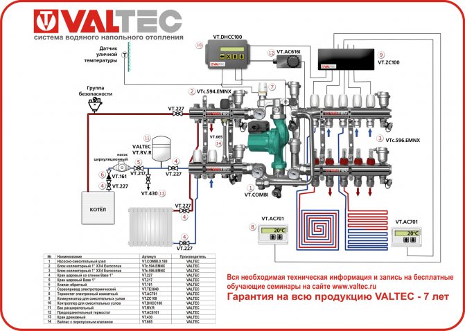
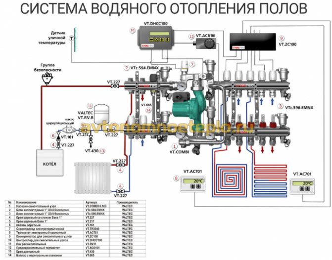
Valtec mixing set connection diagram
- The rated power has a range of 90 - 150 W / m2. Higher values are selected for rooms with high humidity levels.
- When calculating the laying step, it is necessary to focus on the range of 15–30 cm. With this indicator, the specific heating power is in inverse proportional relationship. That is, the larger the step, the less power.

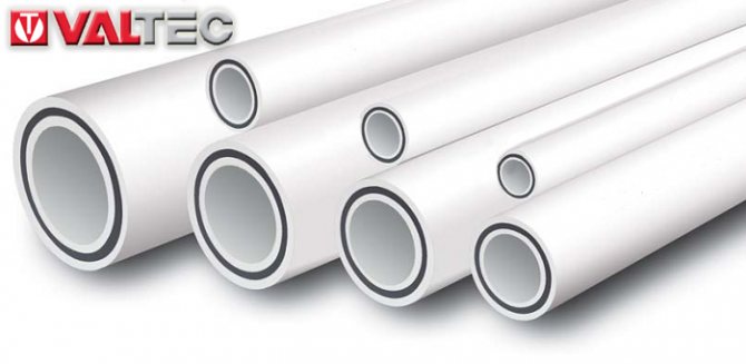
Thermal-mechanical diagram of the pump-mixing unit - Despite the fact that with a large diameter of pipes, a larger amount of coolant passes through them, the thickness of the screed serves as a limiter for this indicator, which is not recommended too large so as not to create excessive load on the floor. Therefore, Valtec pipes made of modern cross-linked polyethylene with an anti-diffusion coating, with a diameter of 16 to 20 mm, are taken into account, and Valtec press fittings act as connecting parts.
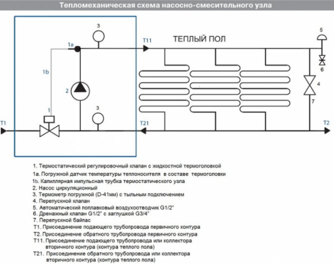
After determining the key parameters, a scheme can be developed on which the most rational pipe laying is determined on an exact scale. After that, their total length is calculated. At the same time, it is considering where the pumping and mixing unit and control elements will be located.
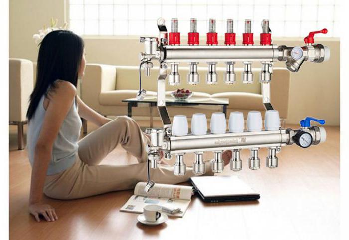
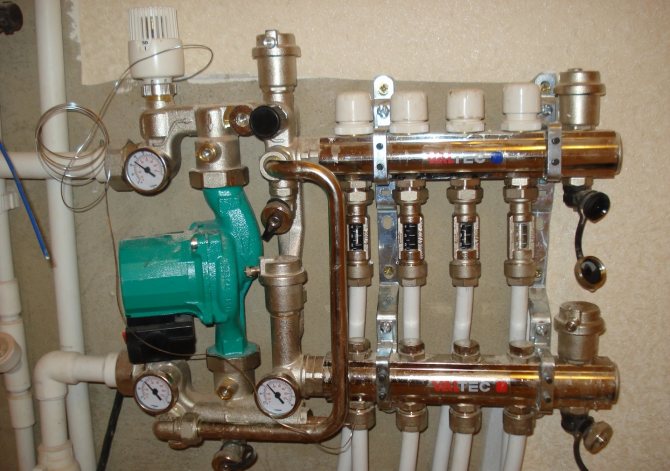
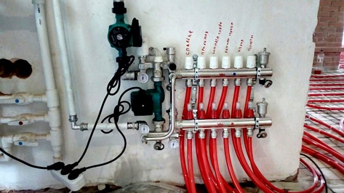
How to assemble a collector?
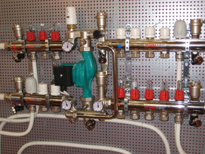
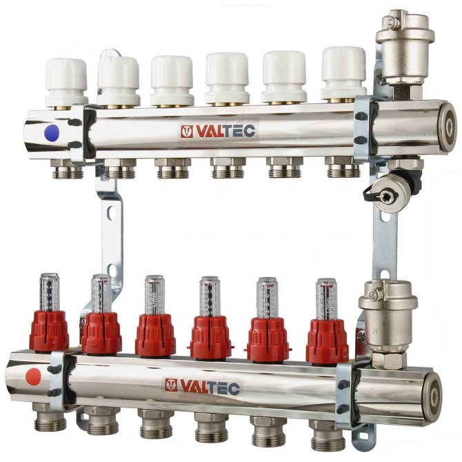
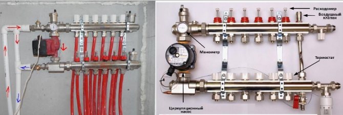
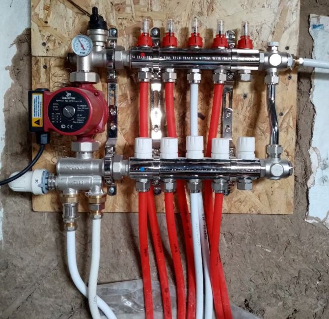
The Valtec distribution block is assembled. The hot pipe already has flow meters installed. There are thermal heads on the cold line, but the product may only have outputs for attaching temperature control devices. They are protected by plastic caps. The manufacturer makes it possible to choose which automation to install: a thermal head, a servo drive.
It is necessary to connect some small elements to the collector group:
- On the right, shut-off valves are connected to the tubes. The set includes 2 pcs.
- A float device is connected to the valves for air discharge.
- Drain valves are connected opposite the air vents on the lower side of the pipes.
- The ends of the comb are closed with plugs.
We recommend: What is a self-leveling underfloor heating?
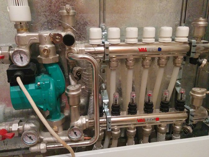
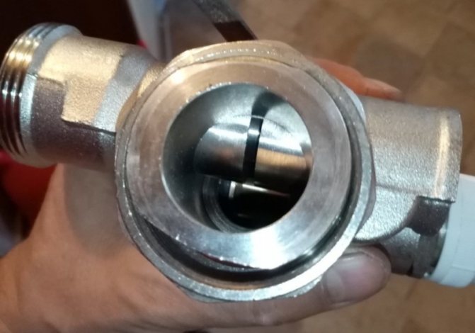
A circulation pump and a three-way or two-way valve are separately connected to the manifold. These devices are sold separately. They are connected to the left of the tube into which the cold coolant enters. Use brass threaded fittings.
Cold and hot circuits are removed from metal pipes that are connected to a boiler or stove. They are connected by means of a bypass at the outlet of the collector group.A circulation pump with a temperature sensor is installed between the circuits.
Adjustment of the rotameter is carried out when testing the heating system. The thermowell must be removed from the device. Using the red ring, the upper sleeve, set the rotameter to zero.
Then, using the same sleeve, the valve is installed on o for large rooms, on o for small rooms. To fix the parameters of the rotameter, the lower ring is turned to the right until it stops.
Return the protective cap to its original place. The variable area flowmeter may not have a retaining ring. In this case, the filling rate of the pipeline is set without fixing. Valve function should be checked regularly.
Collectors "Valtek" for underfloor heating are installed with a liquid heating system. The coolant can be water, antifreeze, glycol fillers, which do not freeze at low temperatures. If the heating system is not used, then the coolant does not need to be drained.
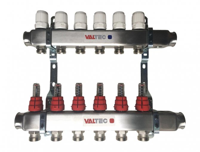
The number of circuits on the distribution block is 3-12 pcs. If necessary, additional equipment can be connected to them in order to increase the flow capacity of the coolant to all rooms in the house.
The comb is fixed on the wall or placed in a manifold cabinet. The manufacturer gives a 10-year warranty for the equipment. Service centers are located in St. Petersburg, Moscow. The unit will serve for over 50 years.
If necessary, the rotameter or thermal head can be replaced without shutting down the heating system. When using a programmable thermostat, the operation of the underfloor heating control unit can be carried out through electronic gadgets.
We recommend: What is National Comfort underfloor heating?
YouTube responded with an error: Access Not Configured. YouTube Data API has not been used in project 268921522881 before or it is disabled. Enable it by visiting https://console.developers.google.com/apis/api/youtube.googleapis.com/overview?project=268921522881 then retry. If you enabled this API recently, wait a few minutes for the action to propagate to our systems and retry.
- Similar posts
- How to install underfloor heating on a concrete floor under a laminate?
- How are XLPE pipes for underfloor heating laid?
- How is the length of the underfloor heating pipe calculated?
- How is the underfloor heating sensor installed?
- How to choose a floor covering for a warm floor?
- How is expanded polystyrene used for underfloor heating?
Key features of the mixing unit
In order for the installed water circuit to function effectively, it is necessary to correctly calculate the entire system and correctly install the Valtec underfloor mixing unit in accordance with the provisions that are reflected in the instructions attached to the kit.
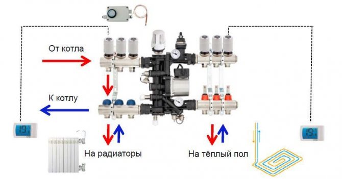
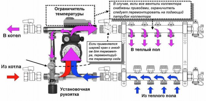
Connection diagram of the mixing unit to different types of heating
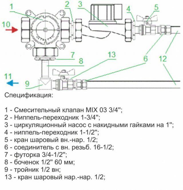
Pump-mixing unit parameters:
- the cross-section of pipes is ¾ ", collectors - 1";
- there are 12 branch pipes in the structure;
- the pumping system is 18 cm long;
- the temperature regime of heated water in the system is maintained up to 90 ° С;
- maximum pressure value - 10 bar;
- throughput - 2.75 m3 / h.
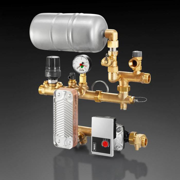
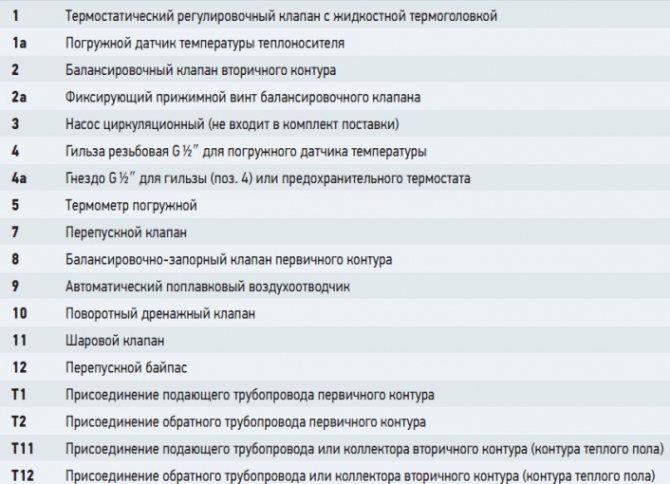
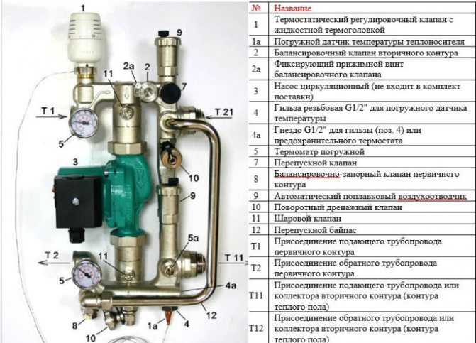
Valtec pump and mixing unit specification
The pipes have an external thread with a Eurocone connection.
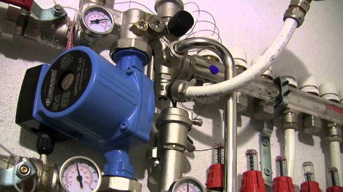
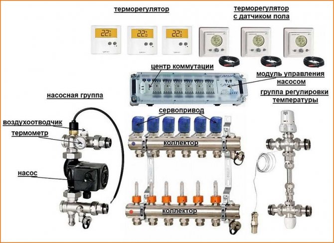
Pump and mixing unit for underfloor heating
Functionality
The main purpose of the pumping and mixing unit is to stabilize the temperature of the coolant when it enters the water circuit by using it to mix water from the return line. Thus, the underfloor heating works optimally without overheating.
The following service elements are included in the Combi assembly:
- drain valves;
- air vents;
- thermometers.
How the Combi unit works
The following organs are used to adjust the knot:
It is permissible to connect an unlimited number of underfloor heating branches to the VALTEC COMBIMIX node with a total power of no more than 20 kW
- a balancing valve on the secondary circuit, which provides mixing in the required proportion of heat carriers from the supply and return pipelines to ensure the specified temperature;
- balancing and shut-off valve on the primary circuit, responsible for supplying the required amount of hot water to the unit.It allows you to completely shut off the flow, if necessary;
- bypass valve to open an additional bypass to ensure pump operation when all control valves are closed.
The connection diagram is designed taking into account the possibility of connecting the required number of floor heating branches to the pumping and mixing unit with a total water consumption not exceeding 1.7 m3 / h. The calculation shows that a similar value of the coolant flow at a temperature difference of 5 ° C corresponds to a power of 10 kW.
If several branches are connected to the mixing unit, it is advisable to select manifold blocks from the Valtec line with the designation VTc.594, as well as VTc.596.
System advantages
The underfloor heating Valtek consists of a mixing unit (which we mentioned above), a manifold block (2 pcs) 1 "x3 / 4 Euroconus, a ball valve Base 1", a ball valve with a squeegee Base 1 ", a check valve, a thermal actuator, room electronic thermostat, communicator for mixing units, controller for mixing units, expansion tank, safety thermostat, drain cock, bypass with bypass valve. For all Valtec products, the manufacturer gives a 7-year warranty, the necessary instructions are attached to each element of the system.
Valtec underfloor heating is gaining more and more popularity every year. This is due to the fact that it has huge advantages over traditional home heating. With such heating, convective air flows are completely absent (as when using fireplaces and central heating radiators), since the heat that will be created by a Valtec water floor heating will rise from the heated floor area upwards, and this heat distribution from floor to ceiling will create maximum comfort for people who will be in the room. The system will provide savings of up to 30%. Valtec underfloor heating has a huge potential to reasonably reduce energy costs for heating water (up to 50 degrees at the maximum value). The system has a self-regulation effect.
In addition, all elements of this system are hidden from view and this means additional visual comfort for people who will live in a house with warm floors. However, like any system, Valtec underfloor heating has its advantages and disadvantages. The advantages of this system include the fact that construction and installation work does not require large costs, because floor elements can be used with all types of floors. The plus will be the fact that this system will successfully replace heating devices and will allow maximum use of the free area of your home, it is autonomous and does not depend on power outages.
The disadvantages include the fact that the water option is possible only in private houses, since there is always the possibility of not noticing damage in time and being flooded, or flooding the neighbors.
Installation Algorithm
After the preliminary calculation of all components is completed, the installation of the warm floor begins directly, which involves the passage of several stages.
Floor heating scheme
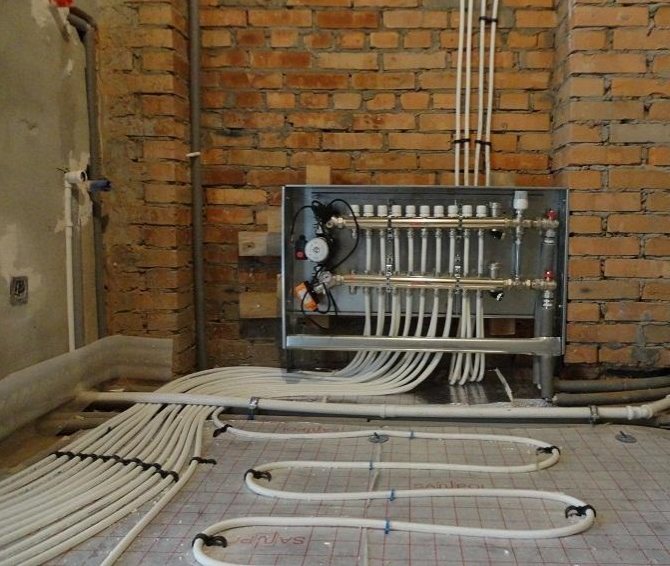
- Installation at a pre-selected location of the manifold cabinet. It houses a module consisting of a manifold block and a pump-mixing unit with ball valves, through which the connection to the high-temperature circuit will be made.
- Preparation of the floor plane. If there are significant irregularities, measures are taken to eliminate them. The most effective option is a rough screed.
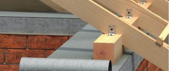
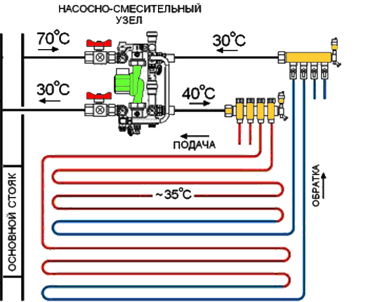
Connection diagram of the pumping and mixing unit to the warm floor - Fixation along the perimeter of the damper tape, which serves as an element that compensates for the possible expansion of the screed that occurs when it is heated. It is attached to the walls so that after finishing there is a surplus, which is cut off before installing the plinth.
- Equipment for thermal insulation by laying on the leveled floor of expanded polystyrene plates with mounting bosses, under which waterproofing is laid, if necessary.
- A previously developed diagram serves as a guide for the subsequent layout of pipes.
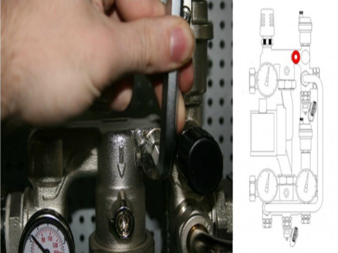
Customization
To connect the pipes to the manifolds, use a pipe cutter to cut to the desired length, a calibrator for chamfering and a compression fitting. It is difficult to carry out a detailed calculation at home, therefore, the instructions must be studied, which detail the setting of the pumping and mixing unit in a certain sequence.
- The thermal head is removed.
- For the balancing valve on the secondary side, the capacity is calculated using the formula.
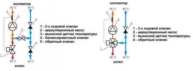
Two variants of the mixing unit
kνb = kνt {[(t1 - t12) / (t11 - t12)] - 1},
where kνt - coefficient = 0.9 valve throughput;
t1 - water temperature of the primary circuit at the supply, ° С;
t11 - temperature of the secondary circuit at the coolant supply, ° С;
t12 - water temperature of the return pipeline, ° С.
The calculated kνb value must be set on the valve.
- Setting the desired mode of operation of the bypass valve when setting the maximum value of the differential pressure of 0.6 bar.
- In order for the underfloor heating to function efficiently, the required pump speed is adjusted. To do this, it is necessary to determine the value of the flow rate of the coolant in the secondary circuit system, as well as the pressure losses that appear in the circuits located after the unit.
Valtec mixing unit equipment
Consumption G2 (kg / s) is determined by the formula:
G2 = Q / [4187 • (t11 - t12)],
where Q is the total thermal power of the water circuit connected to the mixing unit, J / s;
4187 [J / (kg • ° С)] - heat capacity of water.
A special hydraulic calculation program is used to calculate the pressure loss. To determine the pump speed, which is set using the switch, according to the calculated indicators, a nomogram is used, which is in the instructions attached to the underfloor heating structure.
Connection diagram for underfloor heating circuits
- Operations are performed to adjust the balancing valve on the primary circuit.
- The temperature regulator is set to the temperature required for comfortable heating.
- A trial run of the system is in progress.
In the absence of leaks, it remains to make a concrete screed, and after it has completely hardened, lay the floor covering.
VALTEC, Technology of installation of a water heat-insulated floor
The article discusses the practical issues of installing underfloor heating and the most common hydraulic schemes, from the simplest to the most complex, to achieve maximum comfort in the room. The presented circuit options are implemented on the basis of VALTEC equipment.
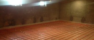
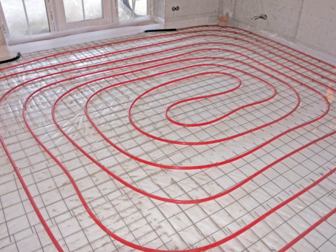
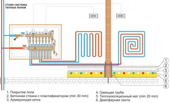
The most common way to implement underfloor heating systems is monolithic floors made by the so-called "wet" method from cement-sand mortar or concrete. The construction of such a floor is presented on fig. one
.
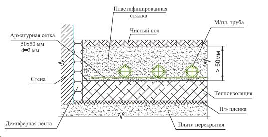
Fig. 1. Underfloor heating construction
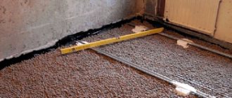
Installation of underfloor heating system begins with surface preparation. The surface must be leveled, irregularities in the area must not exceed ± 5 mm. If necessary, the surface is leveled with an additional screed. Failure to comply with this requirement can lead to "airing" of the pipes.
After leveling the surface, it is necessary to lay a damper tape with a thickness of at least 5 mm along the walls or partitions to compensate for the thermal expansion of the underfloor heating monolith. The tape should be installed along all walls and partitions framing the room, pillars, door frames, columns, bends, etc. The tape should protrude at least 20 mm above the planned height of the floor structure. In the future, it will be covered with a plinth.
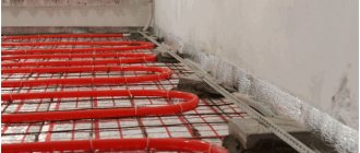
After installing the damper tape, a polyethylene film is laid on the floor to protect against the flow of cement laitance from the mortar and a layer of thermal insulation to prevent heat leakage into the underlying rooms. Foam materials (polystyrene, polyethylene, etc.) or foil-clad thermal insulation materials are used as thermal insulation. It is important that foil-clad thermal insulation materials have a protective film on the aluminum. Otherwise, the alkaline environment of the concrete screed destroys the foil layer within 3-5 weeks. To give strength to the cement-sand screed, a reinforcing mesh is laid.
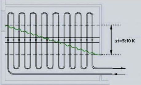
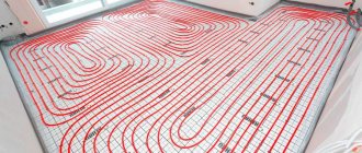
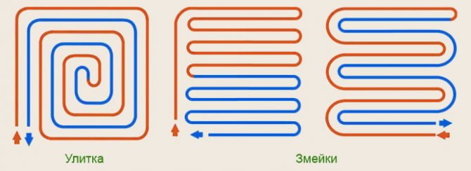
Fig. 2. Laying underfloor heating loops with a "single coil"
Layout of pipes is carried out with a certain step and in the desired configuration specified by the project. In this case, it is recommended to lay the supply pipeline closer to the outer walls. There are several ways to lay floor heating loops.
When laying "single coil" (fig. 2
) the temperature distribution of the floor surface is uneven.
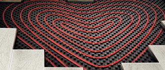
When laying "snail" (fig. 3
), pipes with opposite flow directions alternate, with the hottest section of the pipe adjacent to the coldest one. This leads to a more even temperature distribution over the floor surface.
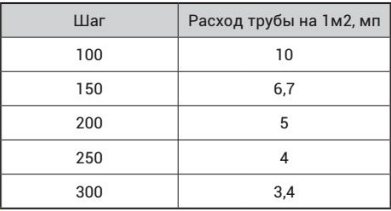
The pipe is laid according to the markings applied to the thermal insulation. The pipes are fastened with anchor brackets every 0.3–0.5 m, or they are held by special projections of thermal insulation mats. The laying step is determined by calculation and lies in the range from 10 to 30 cm. The pipe spacing should not exceed 30 cm, otherwise uneven heating of the floor surface will occur with the appearance of warm and cold stripes. For the convenience of calculating the flow rate of the pipe, depending on the pitch of the pipe and the area of the room, you can use Table 1
.
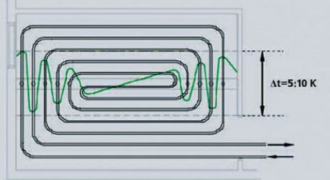
Fig. 3. Laying underfloor heating loops with a "snail"
Areas near the outer walls of a building are called "boundary zones". Here it is recommended to reduce the pipe laying spacing in order to compensate for heat losses through the external enclosing structures. It is not recommended to take the length of one contour (loop) of the warm floor more than 100–120 m. It is preferable that the pressure loss in the loop does not exceed 20 kPa. After laying out the hinges, immediately before pouring the screed, the system is pressurized with a pressure 1.5 times higher than the working pressure, but not less than 0.6 MPa (clause 5.25 of SP 41-102-98).
When pouring a cement-sand screed, the pipe must be under a water pressure of 0.3 MPa at room temperature. The minimum filling height above the pipe surface must be at least 3 cm (the maximum recommended height, according to European standards, is 7 cm). The cement-sand mixture must be at least 150 grade on cement grade 400 at least with a plasticizer. When pouring the screed, it is recommended to use a vibrating screed to remove air bubbles. With a monolithic slab length of more than 8 m or an area of more than 40 m2, it is necessary to provide expansion joints with a thickness of at least 5 mm to compensate for the thermal expansion of the monolith. When pipes pass through the seams, they must have a protective sheath with a length of at least 1 m.
Table 1. Consumption of underfloor heating pipes depending on the area of the room
The underfloor heating system is started only after the screed has completely dried (approximately four days per 1 cm of screed thickness). The water temperature at system start-up must be room temperature. After starting the system, increase the supply water temperature daily by 5 ° C to the design operating temperature.
- The average temperature of the floor surface, in accordance with clause 6.4.8 of SP 60.13330.2012, is recommended to be taken no higher than:
- 26 ° С for premises with constant presence of people;
- 31 ° С for rooms with temporary stay of people and swimming pool bypass paths.
The floor temperature along the axis of the heating element should not exceed 35 ° C.
According to SP 41-102-98, the temperature difference in certain areas of the floor should not exceed 10 ° C (optimally 5 ° C).
The following are the basic schemes for installing a warm floor. Scheme No. 1
solved with the use of the VT.ICBOX thermostatic installation kit, and allows you to automatically maintain the required temperature in the room.
Scheme No. 1 based on the VT.ICBOX thermostatic installation kit
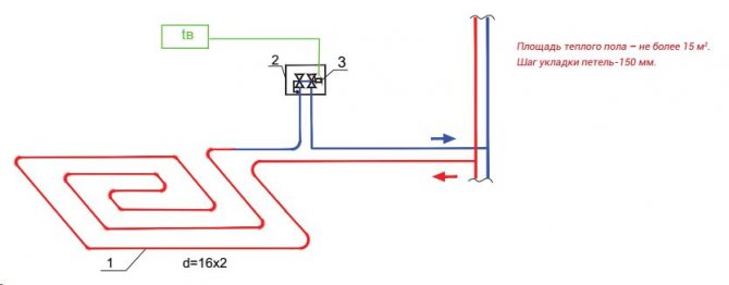
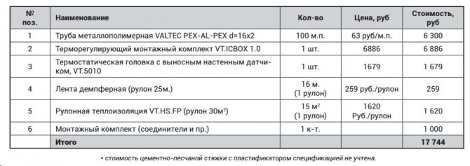
Table 2. Specification of materials for "warm floor" for scheme No. 1 (floor area 15 m 2)
This scheme is used when the coolant in the supply pipeline with a temperature of up to 60 ° C. At higher temperatures of the coolant, it is necessary to apply special technical solutions (partial use of a "warm wall"; use of porous screeds, heat insulation of pipes). The advantages of this scheme include its simplicity and cost effectiveness. It is recommended to use it when laying underfloor heating in small rooms, given that one VT.ICBOX assembly unit can serve only one underfloor heating loop with a length of no more than 100 m. The collector and pump-mixing unit are not required for such a scheme.
The temperature of the heat carrier in the underfloor heating circuit is controlled by a built-in thermostat, which is a part of the VT.ICBOX unit. When the temperature of the heating medium rises above the set value, the thermostat reduces the flow, thereby reducing the floor temperature. For underfloor heating, mounting kits VT.ICBOX1.0 and VT.ICBOX 2.0 are produced. Automatic maintenance of the room temperature in the VT.ICBOX 1.0 unit is carried out using a servo drive or a thermostatic head with an external temperature-sensitive element, and in the VT.ICBOX 2.0 unit - only using a thermostatic head.
- The disadvantage of systems with VT.ICBOX units, when connected to a high-temperature heating system, is the uneven distribution of the coolant temperature along the length of the pipe, which leads to significant differences in floor temperature over adjacent pipes. Therefore, when using underfloor heating based on VT.ICBOX sets, it is recommended:
- use materials that are resistant to high temperatures as a finishing floor covering, for example, ceramic tiles;
- use a screed thickness of at least 50 mm above the pipe, which will exclude abrupt fluctuations in temperature on the floor surface. The greater the thickness of the screed, the less the difference in floor temperatures between adjacent pipes;
- to lay pipes "snail". In this case, "hot" pipes alternate evenly with "cold" ones, which will avoid the presence of overheated areas of the floor.
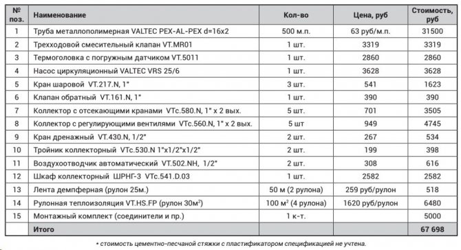
Scheme No. 2 based on the VT.MR01 three-way mixing valve, with a pump in the underfloor heating circuit
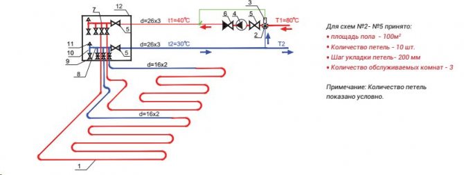
Table. 3. Specification of materials for "warm floor" for scheme No. 2 (per 100 m2 of floor)
IN scheme No. 2
preparation of a heat carrier with low temperature parameters is carried out using a three-way mixing valve VT.MR01 (
pos. 2
), controlled by a thermal head with a remote sensor (
pos. 3
) or a servo driven by the controller. The circulation of the coolant in the underfloor heating circuit is provided by a circulation pump (
pos. four
). When the temperature of the heat carrier in the underfloor heating circuit drops below the set value, the valve passes the required portion of the high-temperature heat carrier into the underfloor heating circuit.
The balancing of the loops with each other is carried out by the control valves that are part of the return manifold (pos. eight
). The scheme is quite simple and workable. The heat transfer of the warm floor is controlled by adjusting the thermal head or by a servo drive. There is no automatic temperature maintenance in each individual room.
Now let's consider how the cost of materials will change if it is required to automatically maintain the air temperature in each room (scheme No. 3
).
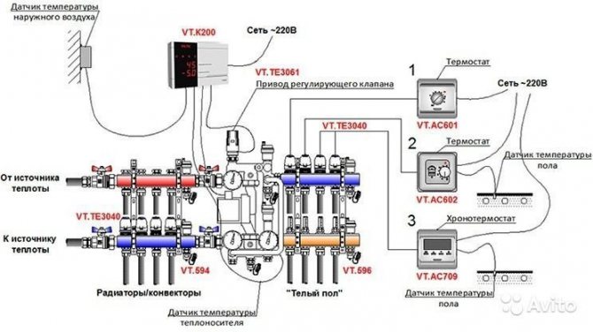
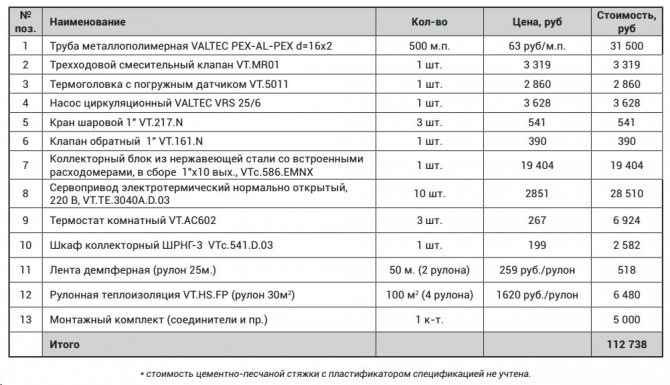
Scheme No. 3 based on the VT.MR01 three-way mixing valve, with a pump in the underfloor heating circuit, with automatic regulation of the indoor air temperature
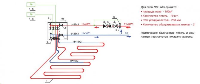
Table 4. Specification of "warm floor" materials for scheme No. 3 (per 100 m2 of floor)
The composition of the VTс.586.EMNX (pos. 7
) includes supply and return manifolds, automatic air vents and drain valves. The supply manifold is equipped with manual control valves with flow meters, which facilitate the process of balancing the loops with each other. The flow meters are configured according to design data. The return manifold is equipped with thermostatic valves with servo drives (
pos. eight
). The servo drive of each loop is controlled by its own room thermostat (pos. 9). The thermostat is installed in each separate room with underfloor heating.
For the possibility of automatic regulation of the temperature in the premises, collector blocks VTс.589.EMNX, VTс.596.EMNX, as well as blocks without flow meters - VTс.588.EMNX, VTс.594.EMNX can be used.
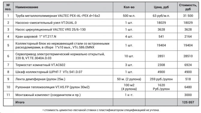
Scheme No. 4 based on the VT.DUAL pumping and mixing unit, with automatic regulation of the indoor air temperature
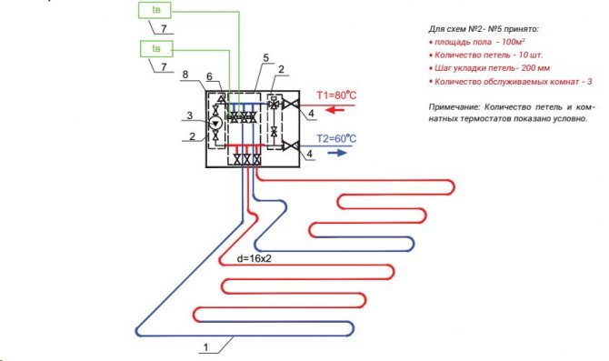
Table 5. Specification of "warm floor" materials for scheme No. 4 (per 100 m2 of floor)
The principle of operation of the mixing unit VT.DUAL (scheme No. 4
) next: the circulation pump (item 3) circulates the coolant through the underfloor heating loops. When the coolant cools down below the setting temperature, the thermostatic valve as part of the unit opens and the secondary circuit is fed with coolant from the primary circuit with a mixture of coolant from the supply manifold of the secondary circuit.
If the set temperature of the secondary circuit is exceeded, the safety thermostat is triggered, stopping the pump. In this case, the circulation of the coolant in the secondary circuit stops, and in the primary circuit it occurs through the bypass. Thus, the unit ensures a constant flow rate in the primary circuit. In the case when the warm loops overlap, the circulation of the coolant in the secondary circuit occurs through the bypass.
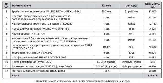
Scheme No. 5 based on the VT.COMBI.S pump-mixing unit, with a weather-dependent controller and automatic controltemperature control in rooms
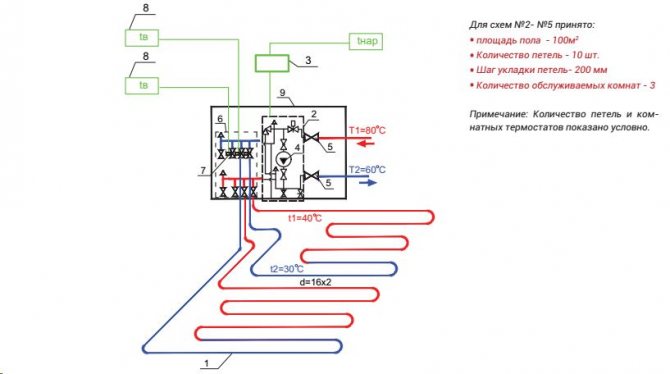
Table 6. Specification of materials for "warm floor" for scheme No. 4 (per 100 m2 of floor)
VT.COMBI.S (scheme No. 5
) are adapted to work with the VT.K200.M controller, which allows automatic weather-dependent control of the temperature of the secondary circuit coolant according to a user-defined schedule.
- The VT.K200.M controller performs the following functions:
- measurement and indication of the outside air temperature;
- measurement and indication of the temperature of the coolant;
- maintaining a comfortable temperature in rooms with any underfloor heating structure and under any climatic conditions;
- data exchange, programming the device over the network via the RS-485 interface (integration into smart home systems);
- emergency shutdown of the circulation pump when the coolant reaches the maximum permissible temperature (60 ° C).
Schemes No. 3, 4, 5
can also be equipped with thermostats with floor temperature sensor VT.AC709. In this case, the regulation will be based on the room temperature, and the floor temperature sensor will play a safety role. It will turn off the supply to the loops of the coolant when the set maximum floor temperature is exceeded. This is important when covering parquet or laminate floors. The VT.AC709 thermostat can be reconfigured to the mode when the floor temperature sensor becomes operational, that is, the control of the coolant supply to the loops will be carried out precisely along it, and the room temperature sensor will become safety. When the air temperature in the room reaches a predetermined critical value, the servo drive will cut off the supply of heat carrier to the loops, regardless of the readings of the floor temperature sensor.
All considered schemes can be combined with each other and supplemented with various equipment.