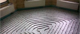
In this article, we will discuss the different types of temperature sensors and how they can be used on a case-by-case basis. Temperature is a physical parameter that is measured in degrees. It is an essential part of any measurement process. Areas requiring accurate temperature measurements include medicine, biological research, electronics, materials research, and thermal performance of electrical products. A device used to measure the amount of heat energy that allows us to detect physical changes in temperature is known as a temperature sensor. They are digital and analog.
Main types of sensors
In general, there are two methods for obtaining data:
1. Contact... Contact temperature sensors are in physical contact with an object or substance. They can be used to measure the temperature of solids, liquids or gases.
2. Contactless... Non-contact temperature sensors detect temperature by intercepting some of the infrared energy emitted by an object or substance and sensing its intensity. They can only be used to measure temperature in solids and liquids. They are unable to measure the temperature of gases due to their colorlessness (transparency).
Symptoms of DTOZH malfunction
The liquid cooling sensor, like any other sensor, can have malfunctions that will ever lead to engine malfunctions.
The main signs that indicate a breakdown of the device:
- increased fuel consumption;
- poor exhaust when the engine is cold;
- problems with starting the engine in cold weather.
Typically, if such a problem occurs, then the sensor does not need to be replaced. The problem may be due to a loose or damaged contact, a wiring problem, or a cooling fluid leak.
Sometimes a cold engine troit and "sausage", and its idle speed jumps from minimum to maximum values per minute, and after a few minutes or from a restart, the situation is corrected.
This problem can be caused by a breakdown of the coolant temperature sensor.
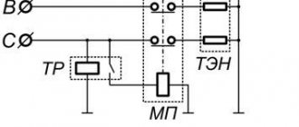
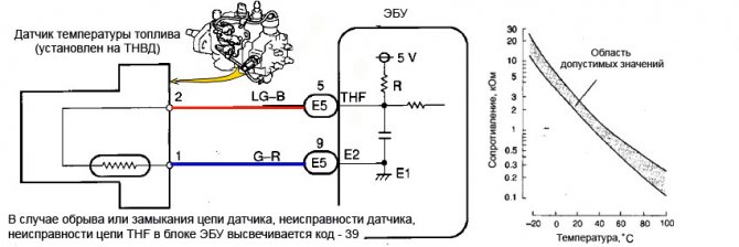
You can check the condition of the device using an ohmmeter. In this case, you do not need to unscrew it. It is not its resistance that is checked, but the mass sensor.
When the sensor is in order, then the resistance tends to infinity, if it is broken, then the resistance is 10 kΩ or less.
Types of temperature sensors
There are many different types of temperature sensors. From simple on / off control of a thermostatic device to complex control systems of water supply, with the function of heating it, used in the processes of growing plants. The two main types of sensors, contact and non-contact, are further subdivided into resistive, voltage and electromechanical sensors. The three most commonly used temperature sensors are:
- Thermistors
- Resistance thermocouples
- Thermocouple
These temperature sensors differ from each other in terms of operational parameters.
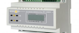
EQUIPMENT DEVELOPMENT TECHNOLOGIES
Lesson about connecting integral temperature sensors with analog output to the Arduino controller. A working draft of the thermometer is presented, and the programmed processing of information from temperature sensors is described.
Previous lesson List of lessons Next lesson
With this publication, I begin a series of lessons about measuring temperature in the Arduino system. In total, 4 lessons are planned on various types of temperature sensors:
- integrated temperature sensors with analog output - LM35, TMP35, TMP36, TMP37;
- silicon temperature sensors of the KTY81 series;
- integrated sensors with a 1-Wire digital interface - DS18B20;
- thermocouples (thermoelectric converters).
In each lesson I will tell you:
- briefly about the principle of operation and parameters of temperature sensors;
- on the schemes for connecting temperature sensors to microcontrollers;
- I'll tell you about the software processing of information from temperature sensors;
- I will give a diagram of a thermometer based on the Arduino board and software for it.
Each lesson will consider a thermometer project based on an Arduino controller working:
- in stand-alone mode with information output on the LED indicator;
- in the mode of communication with a computer, which allows not only displaying the current temperature, but also registering temperature changes with the output of data in graphical form.
Integral temperature sensors with analog voltage output.
With all the variety of these devices, they have the following general qualities:
- output voltage is linearly proportional to temperature;
- the sensors have a calibrated scale factor for the dependence of the output voltage on temperature; additional calibration is not required.
Simply put, to measure temperature using sensors of this type, it is necessary to measure the voltage at the output and, through a scale factor, convert it to temperature.
There are many thermal sensors that fall into this category. I would highlight the following types of temperature sensors:
- LM35;
- TMP35;
- TMP36;
- TMP37.
These are the most common, fairly accurate, inexpensive devices. I have written articles about these sensors. You can look at the links LM35 and TMP35, TMP36, TMP37. All parameters, technical characteristics of devices, typical connection schemes are described in detail there.
Connecting temperature sensors to a microcontroller.
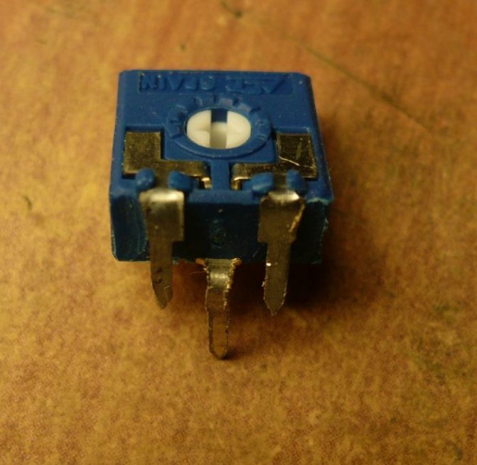
It is most convenient to use sensors in TO-92 package.
The wiring diagram for devices in TO-92 package looks like this.
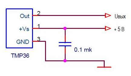
All of the listed sensors will work according to this scheme. Information on other schemes for switching on temperature sensors can be found at links LM35 and TMP35, TMP36, TMP37.
Basic parameters, sensor differences.
The fundamental differences between the listed sensors from each other are that:
- TMP36 is the only one of the listed temperature sensors capable of measuring negative temperatures.
- The sensors have different ranges of temperature measurement.
We are talking about temperature sensors connected according to the above diagram. For example, there is an LM35 switching circuit that allows you to measure negative temperatures. But it is more difficult to implement and requires additional power. It is better to use TMP36 for negative temperatures.
I summarized the main parameters of the LM35, TMP35, TMP36, TMP37 temperature sensors for this circuit in a table.
| A type | Temperature measurement range, ° C | Output voltage offset, mV | Scale factor, mV / ° C | Output voltage at +25 ° C, mV |
| LM35, LM35A | 0 … + 150 | 0 | 10 | 250 |
| LM35C, LM35CA | 0 … + 110 | 0 | 10 | 250 |
| LM35D | 0 … + 100 | 0 | 10 | 250 |
| TMP35 | + 10 … + 125 | 0 | 10 | 250 |
| TMP36 | — 40 … + 125 | 500 | 10 | 750 |
| TMP37 | + 5 … + 100 | 0 | 20 | 500 |
For all temperature sensors, the output voltage can only be positive, but due to the bias, the TMP36 is able to measure negative temperatures. Zero voltage at its output corresponds to a temperature of -40 ° C, and with an output voltage of 0.5 V, the temperature will be 0 ° C. I find the TMP36 to be the most user-friendly analog I / C temperature sensor and I use them quite widely.
Arduino project of thermometer on temperature sensors LM35, TMP35, TMP36, TMP37.
We will develop a thermometer that will:
- In stand-alone mode, display the temperature value on a four-digit seven-segment light-emitting diode (LED) indicator.
- Send the current temperature value to the computer. You can observe it using the Arduino IDE serial port monitor.
- With the help of a special top-level program (I wrote it): display the measured temperature on the computer monitor.
- register temperature changes and display them graphically.
Thermometer circuit based on Arduino UNO R3 board.
It is necessary to connect to the Arduino board:
- four-digit seven-segment LED indicator in multiplexed mode;
- temperature sensor TMP36 or similar.
I chose the LED indicator type GNQ-3641BUE-21. It is bright, the size optimal for this task. We connected it to the Arduino board in lesson 20. In this lesson, you can see the documentation for the indicator, connection diagrams. There is also a description of the library for controlling seven-segment LED indicators.
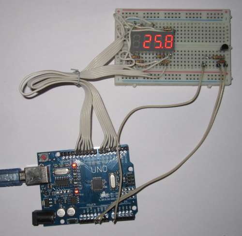
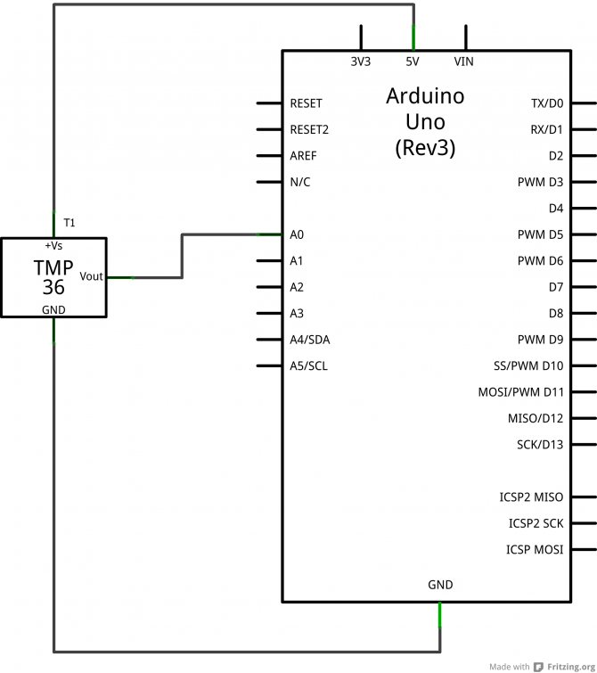
The thermometer circuit based on the Arduino UNO R3 board looks like this.
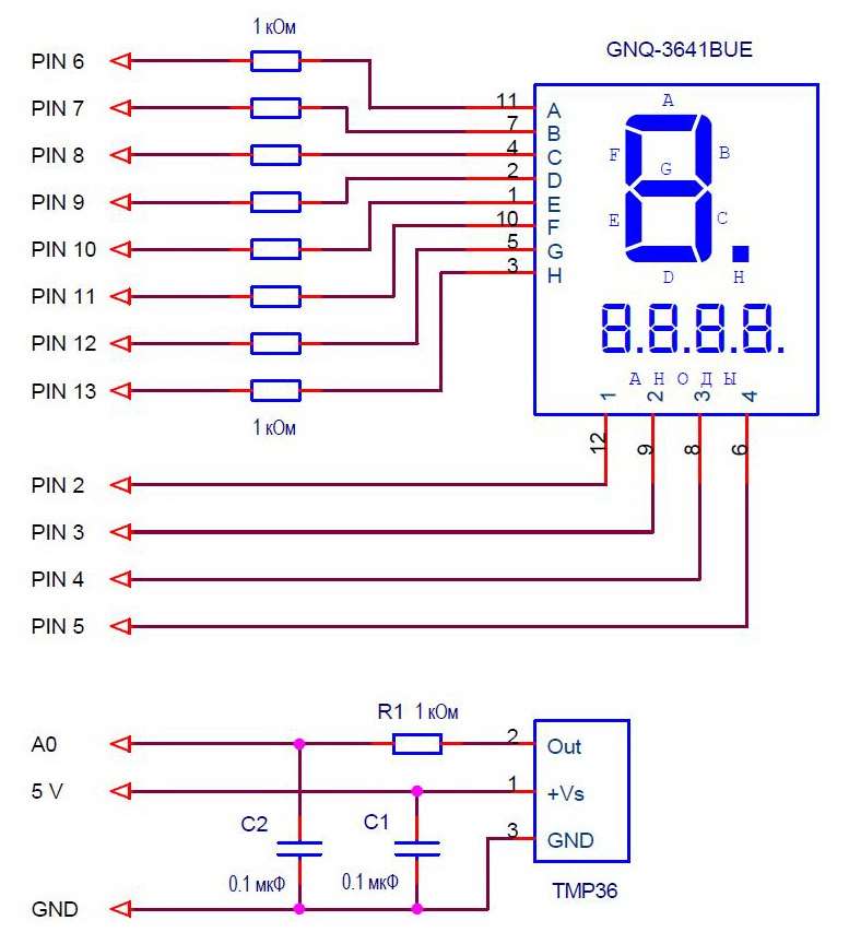
The LED indicator is connected to the controller in multiplexed mode (lesson 19, lesson 20).
The temperature sensor is connected to analog input A0. Capacitor C1 - blocking power supply to the sensor, R1 and C2 - the simplest analog filter. If the thermal sensor is installed near the microcontroller, then the filter can be excluded from the circuit.
TMP35, TMP36, TMP37 allow work on a load with a capacity of up to 10 nF, and LM35 - no more than 50 pF. Therefore, if the sensor is connected to the controller with a long line with significant capacitance, then the resistor R1 must be installed on the sensor side, and the capacitor C2 on the controller side. The blocking capacitor C1 is always installed next to the temperature sensor.
In any case, digital filtering of the signal from the sensor will be implemented in the controller program.
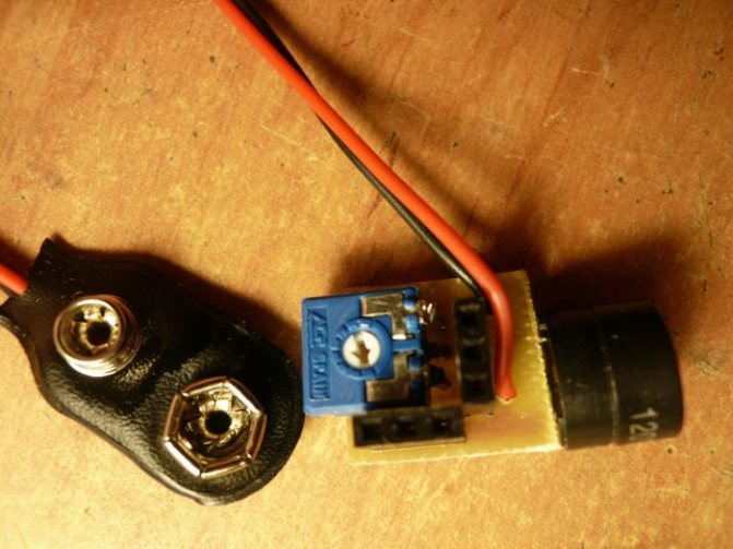
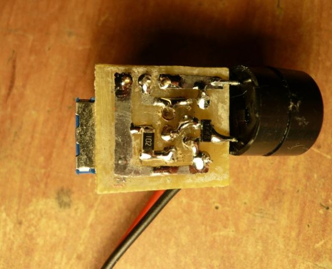
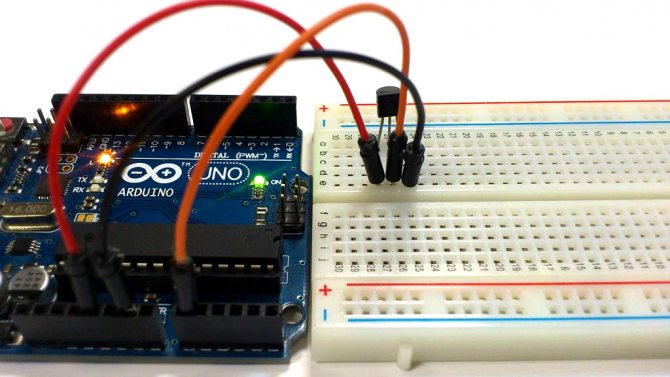
To test it, I assembled the device on a breadboard.
Calculation of temperature.
The principle is simple. To calculate the temperature of the LM35, TMP35, TMP37 sensors, you must:
- Read the ADC code.
- Calculate the voltage at the sensor output as Uout = N * Uion / 1024, where
- Uout - voltage at the output of the temperature sensor;
- N - ADC code;
- Uion - voltage of the reference voltage source (for our circuit 5 V);
- 1024 - the maximum number of ADC gradations (10 bits).
The formulas for calculating the temperature for different sensors with a reference voltage of 5 V look like this.
| Sensor type | The formula for calculating the temperature T (° C), with a reference voltage of 5 V, from the ADC code - N. |
| LM35, TMP35 | T = (N * 5/1024) / 0.01 |
| TMP36 | T = (N * 5/1024 - 0.5) / 0.01 |
| TMP37 | T = (N * 5/1024) / 0.02 |
If digital filtering is used, then it is also necessary to take into account the coefficient for it. You also need to understand that the formulas are written in an easy-to-understand form. In a real program, it is better to calculate the constant part of the formula in advance and use it as a coefficient. This is described in detail in lesson 13. There is also information about reading and digital filtering of an analog signal.
Arduino thermometer program.
The program should perform the following functions:
- read the values of the ADC codes;
- average them (digital filtering) to increase noise immunity;
- calculate the temperature from the ADC code;
- display the temperature value on a four-digit LED indicator in the format: sign;
- tens;
- units;
- tenths of ° C.
The development of the program is based on the usual principle:
- a timer interrupt with a period of 2 ms is implemented;
- in it, a parallel process occurs: regeneration of the LED indicator;
- reading ADC codes and averaging their values;
- software timers.
- synchronization from the program timer 1 sec;
If you read the previous lessons, then everything will be clear.
The libraries MsTimer2.h and Led4Digits.h must be connected. You can download the libraries from Lesson 10 and Lesson 20. There is also a detailed description and examples. See lesson 13 for measuring the voltage of analog inputs.
I will immediately give a sketch of the program.
// thermometer, sensors LM35, TMP35, TMP36, TMP37 #include #include
#define MEASURE_PERIOD 500 // measurement time, * 2 ms #define ADC_RESOLUTION 4.8828125 // ADC resolution, mV (5000 mV / 1024) #define OFFSET 500. // output voltage offset, mV (for TMP36) #define SCALE_FACTOR 10. // scale factor, mV (for TMP36)
int timeCount; // counter of measurement time long sumA0; // variable for summing ADC codes long avarageTemp; // average temperature value (sum of ADC codes, average value * 500) boolean flagTempReady; // sign of readiness of temperature measurement float temperature; // calculated temperature, ° C
// indicator type 1; outputs of categories 5,4,3,2; segment pins 6,7,8,9,10,11,12,13 Led4Digits disp (1, 5,4,3,2, 6,7,8,9,10,11,12,13);
void setup () {MsTimer2 :: set (2, timerInterrupt); // set the timer interrupt period to 2 ms MsTimer2 :: start (); // enable timer interrupt Serial.begin (9600); // initialize the port, speed 9600}
void loop () {
if (flagTempReady == true) {flagTempReady = false; // data is ready
// calculating the temperature temperature = (avarageTemp * ADC_RESOLUTION / 500. - OFFSET) / SCALE_FACTOR;
// displaying the temperature on the indicator if (temperature> = 0) {// positive temperature disp.print ((int) (temperature * 10.), 4, 1); } else {// negative temperature disp.digit [3] = 0x40; // minus is displayed disp.print ((int) (temperature * -1 * 10.), 3, 1); } disp.digit [1] | = 0x80; // light the point of the second digit // transfer the temperature to the computer Serial.println (temperature); }}
// ————————————— interrupt handler 2 ms void timerInterrupt () {disp.regen (); // regenerate the LED indicator
// measuring the average temperature timeCount ++; // +1 counter of averaging samples sumA0 + = analogRead (A0); // summation of ADC channel A0 codes
// check the number of averaging samples if (timeCount> = MEASURE_PERIOD) {timeCount = 0; avarageTemp = sumA0; // overload the mean value sumA0 = 0; flagTempReady = true; // sign that the result is ready}}
You can download the sketch from this link:
Register and pay. Only 40 rubles. per month for access to all site resources!
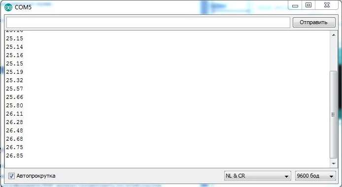
Loading, checking. We start the serial port monitor and check the data on the computer.
The program is designed for TMP36 sensors, but it is easy to adapt to other types of sensors. To do this, it is enough to change the values of the scale factor and offset, specified at the beginning of the program with the #define statements.
| Sensor type | Factor and bias |
| LM35, TMP35 | #define OFFSET 0. #define SCALE_FACTOR 10. |
| TMP36 | #define OFFSET 500. #define SCALE_FACTOR 10. |
| TMP37 | #define OFFSET 0. #define SCALE_FACTOR 20. |
Resolution and accuracy of the thermometer.
The resolution of the ADC in our circuit is 5 V / 1024 = 4.88 mV.
Thermometer resolution:
- at a scale factor of 10 mV / ° C (LM35, TMP35, TMP36 sensors) is less than 0.5 ° C;
- at a scaling factor of 20 mV / ° C (TMP37 probe) is less than 0.25 ° C.
Quite decent parameters.
As for the measurement error, it is somewhat worse.
The measurement error of the sensors themselves is:
- no more than 0.5 ° C for LM35;
- no more than 1 ° C for TMP35, TMP36, TMP37.
Measurement error of the ADC of the Arduino board.
In our device, we used a 5 V reference voltage, i.e. power supply voltage. In Arduino UNO R3 boards, the 5 V voltage is formed on the NCP1117ST50 linear regulator. Specifications in PDF format can be viewed at this link NCP117.pdf. The stability of the output voltage of this microcircuit is quite high - 1%.
Those. the total measurement error of the thermometer is no more than 2%.
It can be slightly increased by measuring the voltage of 5 V on the board and setting the ADC resolution in the parameter not to 5 V, but to a more accurate value. On my board, the voltage turned out to be 5.01 V. In my program, you need to fix:
#define ADC_RESOLUTION 4.892578 // ADC resolution, mV (5010 mV / 1024)
Using an external voltage reference for the Arduino board.
But there is a radical way to improve both ADC measurement accuracy and resolution. This is the use of an external voltage reference.
The most common source of stable voltage is LM431, TL431, etc. I am going to write an article about this microcircuit. For now, I will give a link to the information - LM431.pdf.
I will give the LM431 switching circuit as a 2.5 V reference voltage for the Arduino board.
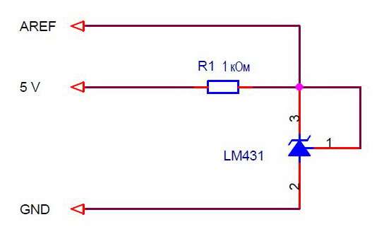
In the program, you need to change the line that determines the resolution of the ADC:
#define ADC_RESOLUTION 2.44140625 // ADC resolution, mV (2500 mV / 1024)
And in setup () connect an external voltage reference:
analogReference (EXTERNAL); // external reference voltage
As a result, the resolution will decrease by 2 times, and the stability will decrease by an order of magnitude. Just all the same, in order to improve accuracy, it is necessary to measure the real voltage of the LM431 with a voltmeter and correct it in the program.
Such modification of the thermometer is absolutely necessary if the device is powered from an unstabilized power source with a voltage close to 5 V, for example, from galvanic batteries or a rechargeable battery. In this case, there is no need to talk about the stability of the power supply, and without stabilization of the reference voltage source, the measurement will be very conditional.
Top-level thermometer program.
Looking at the running lines of numbers in the Arduino IDE monitor window quickly gets boring. I just want to see the temperature value. In addition, for the practical use of the thermometer with a computer, the Arduino IDE software must be installed. Not all computers have it. Also, people are often interested in temperature changes, the process of heating or cooling over time.I would like to be able to register temperature changes and display them graphically.
To do this, I wrote a simple top-level program that:
- displays the current temperature value;
- registers the temperature change with a discreteness of 1 sec;
- displays information about temperature changes in graphical form.
This program can be used both with the thermometer from this article and for the thermometers of the subsequent lessons with other types of sensors.
The program works under the operating systems Windows 95, 98, XP, 7. I have not tried the rest.
Installing the application.
- Download the archive file Thermometer.zip:
Register and pay. Only 40 rubles. per month for access to all site resources!
- Unzip it to your working folder. You can leave the folder from the Thermometer archive.
The application consists of two files:
- Thermometer.exe - executable file;
- Conf.txt - configuration file.
There is no need to install the program, just run the Thermometer.exe file.
Connecting the thermometer to the computer.
Data exchange between the computer and the controller is carried out through the COM port. The port can be real or virtual.
The most convenient way is to use the virtual port, which is created by the driver of the Arduino board. The port appears when the board is connected to the computer. You don't need to launch the Arduino IDE. The port number can be viewed: Control Panel -> System -> Device Manager -> Ports (COM and LPT)
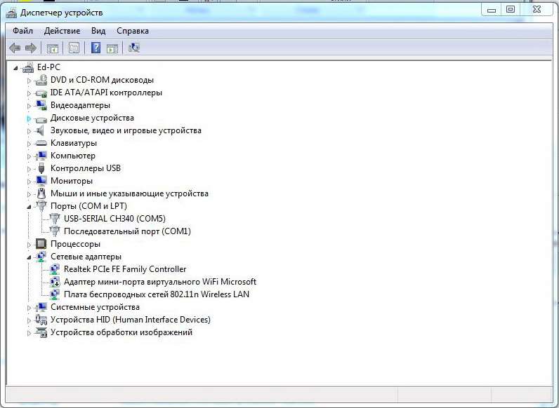
I have COM5.
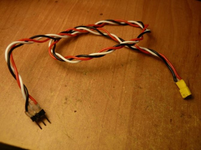
You can connect your computer via some kind of USB-UART bridge. I am using PL2303 USB UART Board modules. How to connect is written in the article about the program Monitor the refrigerator on the Peltier element.
If the computer has a standard COM port (RS232 interface), then you do not need to install any drivers. To connect the controller in this case, it is necessary to use an RS232 - TTL level converter, ADM232, SP232, MAX232 microcircuits and the like.
There are many connection options. The main thing is that a COM port, virtual or real, is formed on the computer.
First launch of the program.
Before starting the program, a virtual COM port must have already been created on the computer. And since the port is created when connecting to the Arduino board connector, this means that you first need to connect the board to the computer.
Then run the Thermometer.exe program. Some COM port is written in the program configuration file. The program will try to open it at startup. If it does not work, then it will display a message with the number of the erroneous port.
Click OK and the program window will open. There will be dashes instead of temperature. There is no data.
Select the port selection mode from the menu (top). A selection window will open.
Set the port number for your board. Each port has its state written. Naturally, you need to choose from ports labeled “free”.
Close the window. The selected COM port will be saved in the configuration file and will always be called when the program starts. You do not need to set the port every time you start the program.
If the board is turned on, the program is loaded, everything is working correctly, then once a second a circle-LED should flash in front of the temperature value. It flashes when new data arrives.
Registrar.
There is a recorder in the program that allows you to observe the dynamics of temperature changes. The recorder turns on automatically when the program starts. It records temperature values in 1 second time increments. The maximum registration time is 30,000 seconds or 8.3 hours.
To view the recording results, press the "Recorder" menu tab.
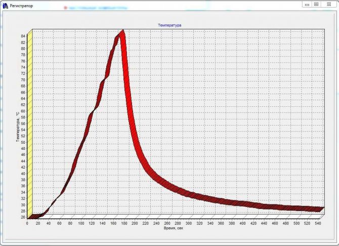
It was I who heated the sensor with a soldering iron.
You can enlarge the fragment by selecting a rectangular area with the right mouse button pressed. The area must be selected from left to right, top to bottom.
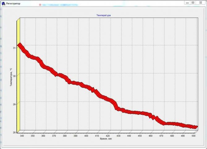
Selecting an area with the mouse from left to right, bottom to top will return the display of all graphical information. It's simple.
This program will be used in the next three lessons with other types of temperature measurement projects.
In the next lesson, we will measure temperature using KTY81 series silicon sensors.
Previous lesson List of lessons Next lesson
Support the project
2
Author of the publication
offline 1 hour
Edward
139
Comments: 1585Posts: 161Registration: 13-12-2015
Thermistor
A thermistor is a sensitive resistor that changes its physical resistance with temperature. Typically, thermistors are made of a ceramic semiconductor material such as cobalt, manganese, or nickel oxide and are coated with glass. They are small flat sealed discs that react relatively quickly to any temperature change.
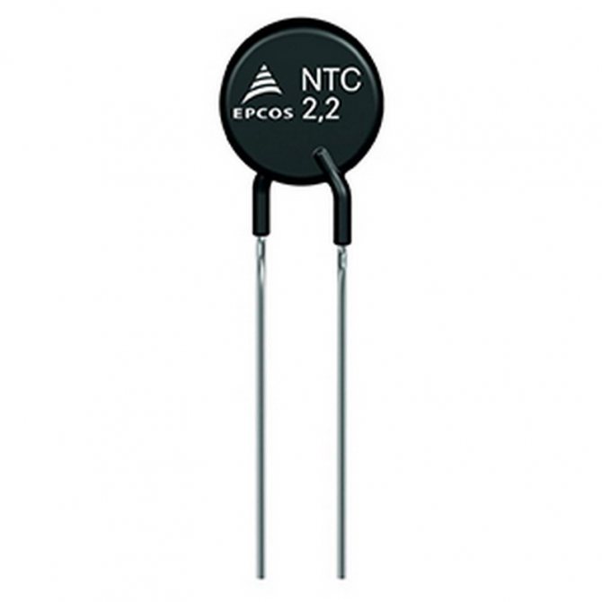
Due to the semiconducting properties of the material, thermistors have a negative temperature coefficient (NTC), i.e. resistance decreases with increasing temperature. However, there are also PTC thermistors whose resistance increases with increasing temperature.
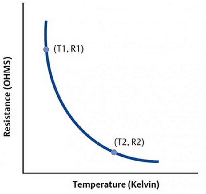
Thermistor schedule
Advantages of thermistors
- High speed of response to temperature changes, accuracy.
- Low cost.
- Higher resistance in the range of 2,000 to 10,000 ohms.
- Much higher sensitivity (~ 200 ohm / ° C) within a limited temperature range of up to 300 ° C.
Temperature dependences of resistance
The dependence of resistance on temperature is expressed by the following equation:
Where A, B, C - these are constants (provided by the terms of calculation), R - resistance in Ohms, T - temperature in Kelvin. You can easily calculate the change in temperature from a change in resistance or vice versa.
How to use a thermistor?
Thermistors are rated for their resistive value at room temperature (25 ° C). A thermistor is a passive resistive device, so it requires the production of monitoring the current output voltage. As a rule, they are connected in series with suitable stabilizers forming a mains voltage divider.
Example: Consider a thermistor with a resistance value of 2.2K at 25 ° C and 50 ohms at 80 ° C. The thermistor is connected in series with a 1 kΩ resistor through a 5 V supply.
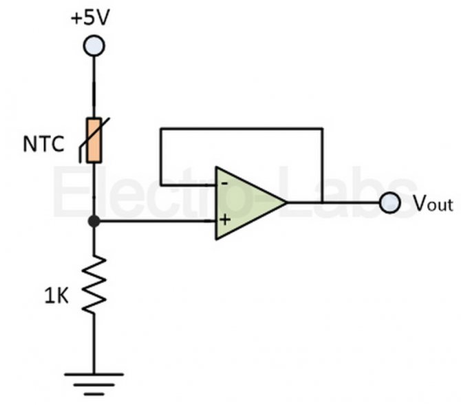
Therefore, its output voltage can be calculated as follows:
At 25 ° C, RNTC = 2200 ohms;
At 80 ° C, RNTC = 50 ohms;
However, it is important to note that at room temperature the standard resistance values are different for different thermistors, as they are non-linear. A thermistor has an exponential temperature change, and therefore a beta constant, which is used to calculate its resistance for a given temperature. The resistor output voltage and temperature are linearly related.
Connecting DS18B20 sensor to microcontroller
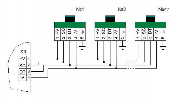
Typical diagram for connecting DS18B20 sensors to a microcontroller:
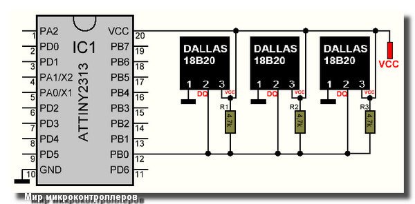
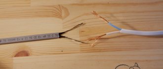
As you can see from the diagram, the DS18B20 sensor (or sensors) are connected to the microcontroller, if they have a common power supply, with three conductors: - conclusion No. 1 - common wire (mass, earth) - conclusion number 2 - aka DQ, through which communication between MK and DS18B20 takes place, is connected to any pin of any port of MK. The DQ pin must be "pulled up" through the resistor to the positive power supply - conclusion No. 3 - sensor power supply - +5 volts If the device uses several temperature sensors, then they can be connected to different pins of the MK port, but then the volume of the program will increase. It is better to connect the sensors as shown in the diagram - in parallel, to one pin of the MK port. Let me remind you about the size of the pull-up resistor: “The resistance of the resistor must be chosen from a compromise between the resistance of the cable used and external noise. The resistance of the resistor can be from 5.1 to 1 kOhm. For cables with high conductor resistance, a higher resistance must be used.And where there is industrial interference, choose a lower resistance and use a cable with a larger wire cross-section. For telephone noodles (4 cores), a 3.3 kΩ resistor is required for 100 meters. If you use "twisted pair", even category 2, the length can be increased up to 300 meters "
Resistive temperature sensors
Temperature-resistance sensors (RTDs) are made of rare metals, such as platinum, whose electrical resistance varies with temperature.
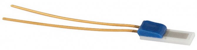
Resistive temperature detectors have a positive temperature coefficient and, unlike thermistors, provide high temperature measurement accuracy. However, they have poor sensitivity. Pt100 is the most widely available sensor with a standard resistance value of 100 ohms at 0 ° C. The main disadvantage is the high cost.
The advantages of such sensors
- Wide temperature range from -200 to 650 ° C
- Provide high drop current output
- More linear compared to thermocouples and RTDs
Thermocouple
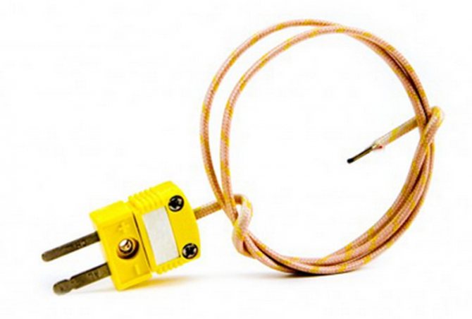
Thermocouple temperature sensors are most commonly used because they are accurate, operate over a wide temperature range from -200 ° C to 2000 ° C, and are relatively inexpensive. A thermocouple with a wire and a plug in the photo below:
Thermocouple operation
A thermocouple is made of two dissimilar metals welded together to produce a potential difference over temperature. From the temperature difference between the two junctions, a voltage is generated that is used to measure the temperature. The voltage difference between the two junctions is called the Seebeck effect.
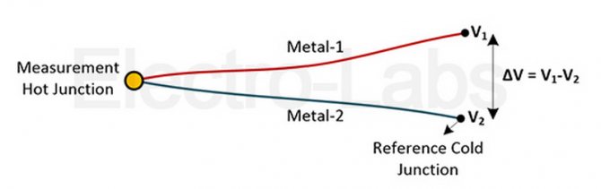
If both compounds are at the same temperature, the potential for difference in different compounds is zero, i.e. V1 = V2. However, if the junctions are at different temperatures, the output voltage relative to the temperature difference between the two junctions will be equal to their V1 - V2 difference.
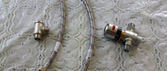
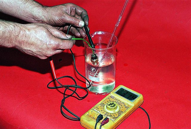
Full sensor check
For it, you will need, again, a multimeter and a thermometer that can be immersed in water and shows up to 100 ° C. Execution order:
- Connect the multimeter wires to the sensor contacts.
- Dip the item to be checked and the thermometer into a container of water.
- Heat the water by monitoring the temperature and readings of the multimeter.
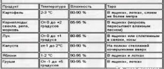
Checking the coolant temperature sensor
As you have seen from the table, the resistance of the sensor changes with temperature. If they match the table, he is fine. When the resistance values change, there should be no sharp jumps - this is also a sign of a malfunction. If you do not have a suitable thermometer, you can only test with boiling water, that is, at 100 ° C. Resistance in this case should be approximately equal to 180 ohms.