The opinion of the owners of country houses about the system
According to most owners of suburban real estate, this scheme is really very effective - the Tichelman loop. This system has earned excellent reviews. A very comfortable microclimate is established in a house with its correct design and assembly. At the same time, the equipment of the system itself rarely breaks down and serves for a long time.
Not only the owners of residential buildings, but also the owners of summer cottages speak well of the Tichelman loop. The heating system in such buildings is often used irregularly during the cold season. If the wiring is done according to a dead-end scheme, when the boiler is turned on, the rooms warm up extremely unevenly. Of course, there are no such problems with a passing system. But the cost of assembling heating according to such a scheme is really more expensive than according to a dead-end one.
Installation procedure
The work consists of the following operations:
- Boiler installation. The required minimum height of the room for its placement is 2.5 m, the allowable volume of the room is 8 cubic meters. m. The required power of the equipment is determined by calculation (examples are given in special reference books). Approximately for heating 10 sq. m requires a power of 1 kW.
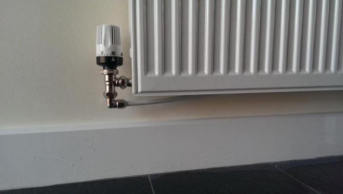
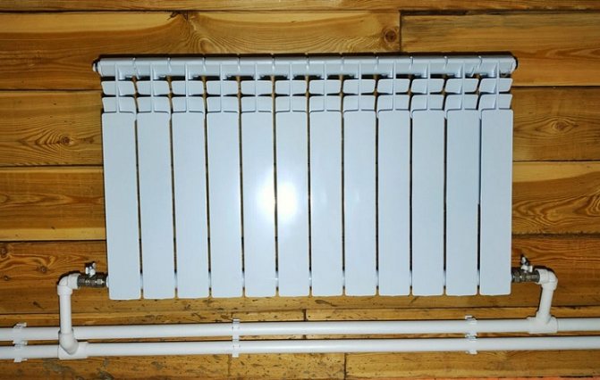
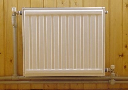
- Mounting of radiator sections. The use of biometric products in private homes is recommended. After selecting the required number of radiators, their location is marked (as a rule, under window openings) and fastened using special brackets.
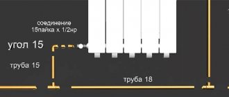
- Pulling the line of the associated heating system. It is optimal to use metal-plastic pipes that successfully withstand high temperature conditions, which are distinguished by their durability and ease of installation. The main pipelines (supply and "return") from 20 to 26 mm and 16 mm for connecting radiators.
- Installation of a circulation pump. It is mounted on the return pipe near the boiler. The tie-in is carried out through a bypass with 3 taps. A special filter must be installed in front of the pump, which will significantly increase the life of the device.
- Installation of an expansion tank and elements that ensure the safety of the equipment. For a heating system with a passing flow of the coolant, only membrane expansion vessels are selected. The elements of the safety group are supplied complete with the boiler.
For tracing the main line of doorways in utility rooms and utility rooms, it is allowed to mount pipes directly above the door. In this place, in order to exclude the accumulation of air, automatic air vents are necessarily installed. In residential areas, pipes can be laid under a door in the floor body or bypassing an obstacle using a third pipe.
Tichelman's scheme for two-story houses provides for a certain technology. Piping is carried out with the tying of the entire building as a whole, and not each floor separately. It is recommended to install one circulation pump on each floor while maintaining equal lengths of return and supply pipelines for each radiator separately in accordance with the basic conditions of the associated two-pipe heating system. If you install one pump, which is quite acceptable, then if it fails, the heating system in the entire building will turn off.
Many experts consider it advisable to install a common riser on two floors with separate piping on each floor.This will allow taking into account the difference in heat loss on each floor with the selection of pipe diameters and the number of required sections in radiator batteries.
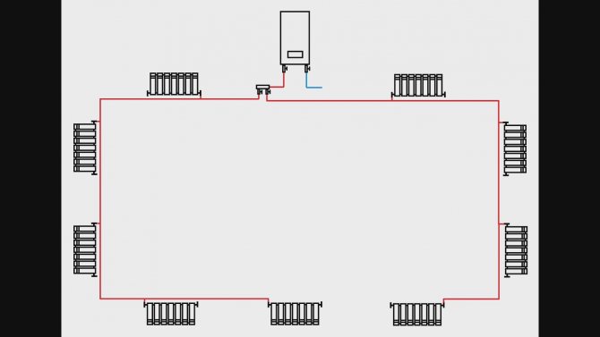
A separate passing heating scheme on the floors will greatly simplify the setup of the system and will allow for optimal balancing of the heating of the entire building. But in order to obtain the desired effect, it is imperative that a tie-in into the path of the balancing crane is required for each of the two floors. The taps can be placed side by side directly next to the boiler.
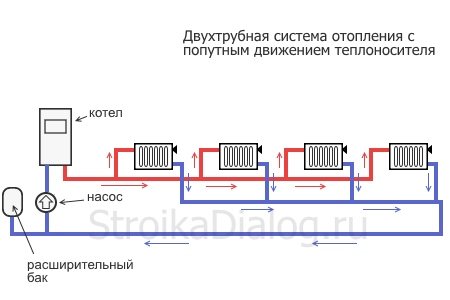
Two-pipe heating system, different schemes (Tichelman scheme)
- Video creator: Marat Ishmuratov
- Author's channel: https://www.youtube.com/channel/UCyrdKMbXbRXONaCrEY0rnPg
- Video:
We will consider a two-pipe heating system, options for connecting it with advantages and disadvantages.
- First connection diagram
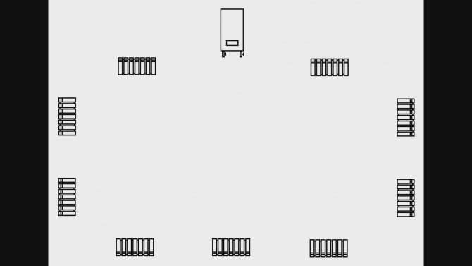
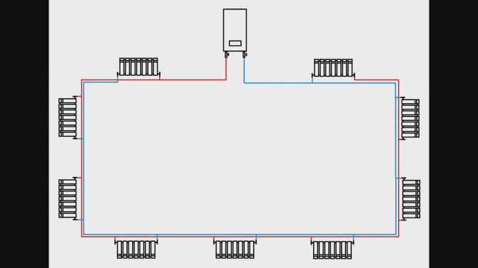
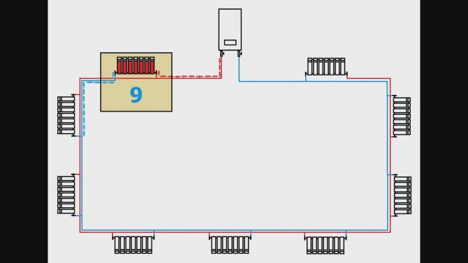
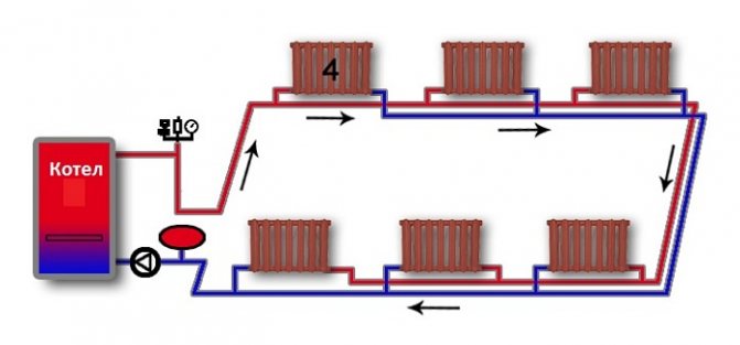
Any system has a boiler for heating and radiators located around the perimeter of the house.
Through this pipe, the hot coolant is supplied from the boiler, all radiators pass through in order, giving off heat, it unfolds on the latter, and through the second pipe, collecting return from all radiators, it returns back to the boiler.
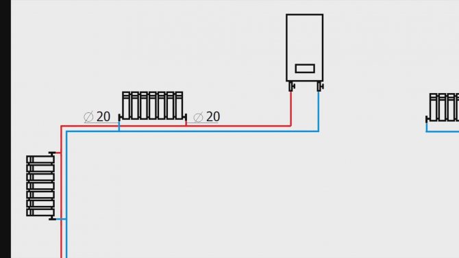
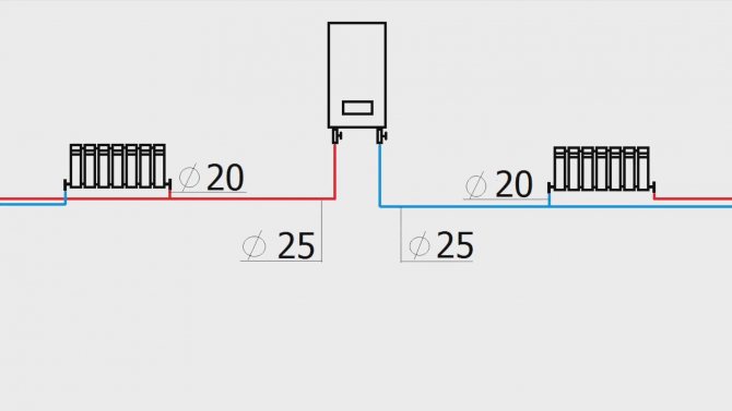
Usually, with this scheme, the main supply and return pipes have a diameter of 25 mm, and the radiators are connected with pipes with a diameter of 20 mm.
This connection diagram works as follows. The hot coolant leaves the boiler, reaches the first radiator, heats it up and then returns to the boiler via the return flow.
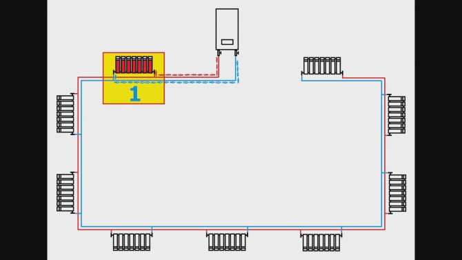
Thus, this radiator is the first in the supply and return, in the most favorable conditions. He has the strongest feed and return. Then the coolant goes to the second radiator, heats it up, and returns back to the boiler. Accordingly, this radiator is the second in the supply and return, and also has favorable conditions.
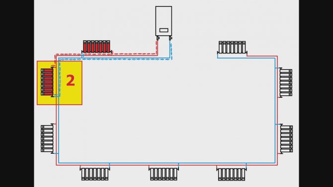
This is how all radiators are warmed up, up to the last, ninth in the supply and return.
He has the least favorable working conditions, the weakest feed and return.
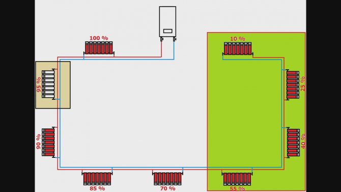
If we run this circuit with open valves, we get the following: the first radiator will start at 100%, the second at 85%, the third at 65%, the fourth at 40% and the fifth at 10%. Remaining radiators will not start by themselves.
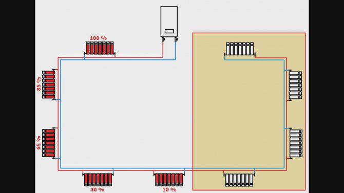
Of course, there are different houses, and the length of the pipes, and the number of sections. Therefore, the system may work better or worse, but in any case, in order to make all the radiators work, it is necessary to artificially create resistance for the coolant in the first radiators using balancing valves.
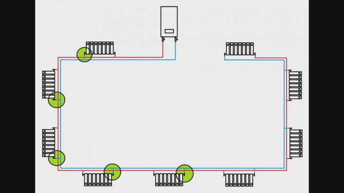
After balancing, the first radiator will heat up by 100%, the second by 95%, the third by 90%, and so on until the last radiator. At the same time, the last few radiators will never start more than 60% of their capacity.
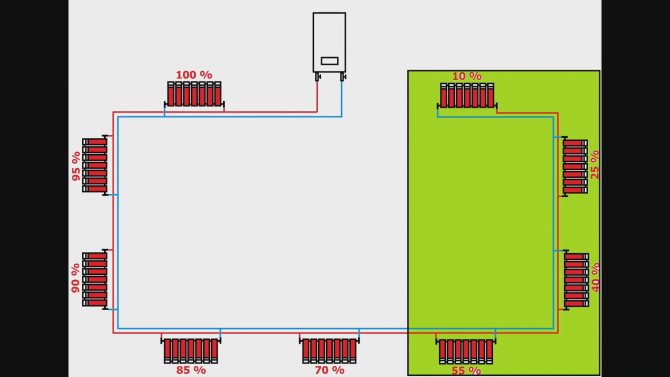
The latest radiators will perform the worst. This scheme has another drawback. For example, in this room you decide to turn down the power of the radiator or close it completely.
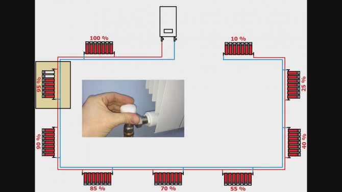
In this case, you will affect the operation of other radiators:
If you reduce the power of your radiator, others will start to heat a little better, if you add return, they will work worse. You can improve this scheme, for example, increase the diameter of the supply and return pipes, or add sections to each radiator.
The system will turn out to be more expensive, while these radiators will not work 100%:

Accordingly, one part of the circuit is clamped, and the second cannot start and work normally.
From the point of view of hydraulics, the boiler, the circulation pump, and the entire system are not in the best conditions.
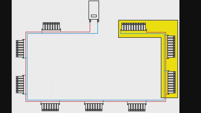
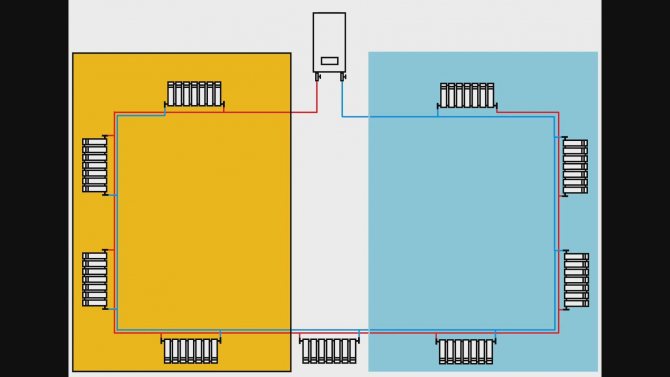
- The second option for connecting these radiators in a two-pipe system
From the boiler, the supply is connected to the collector at two outputs, then different branches are connected to different radiators:
In the same way, the return flow is connected through a double collector. Two radiator circuits are formed.
Shorter supply and return circuits are obtained, but in this case, balancing will have to be done not only on the radiators, but also on the collector of the radiator circuits, because in practice it practically does not happen that both branches are exactly the same and have the same hydraulic resistance.
With this scheme, the radiators will work much better, even the latest radiators, but they will not start at 100% of their thermal power.
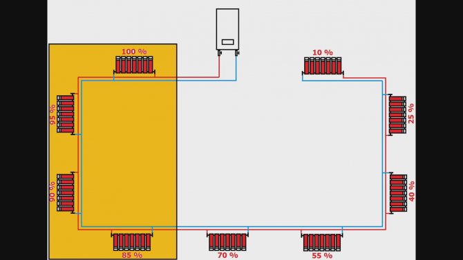
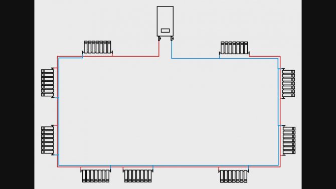
- Third connection diagram
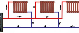
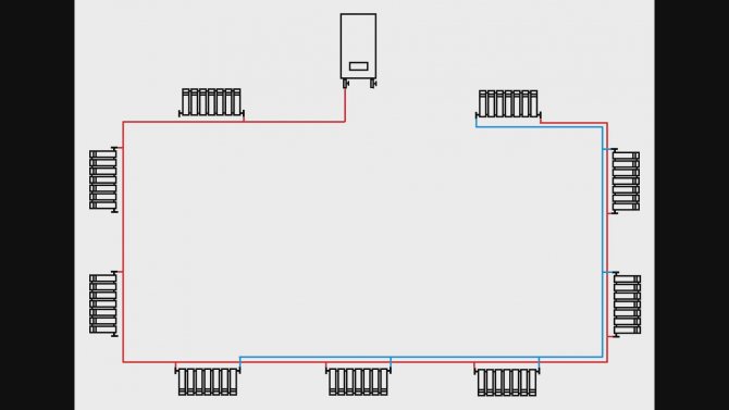
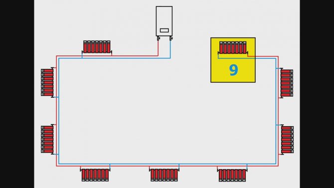
This circuit is called the Tichelman circuit. In it, the flow goes to the last radiator, and the return flow starts from the last radiator, and the output is this:
Here, too, the supply and return pipes have a diameter of 25 mm, and pipes with a diameter of 20 mm go to the radiators.
Let's see how this connection diagram will work. From the boiler, the coolant enters the first radiator, and the return flow begins from it.
Thus, this radiator is the first in the flow and the ninth in the return, that is, it has the strongest flow and the weakest return. Then the coolant heats up the next radiator, which is the second in the flow and the eighth in the return.
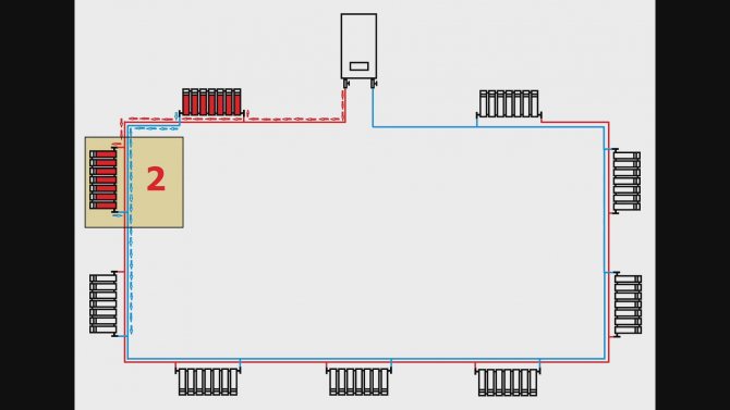
Compared to the previous one, it has a slightly worse flow, but the return flow is slightly better. Consider this radiator:
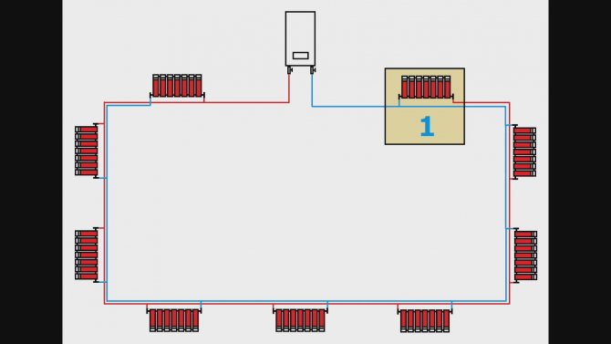
It turns out to be the ninth in the flow and the first in the return, that is, it has the weakest flow and the strongest return, since it is closest to the boiler on the return line:
Consider this radiator:
He turns out to be eighth on the serve and second on the return. With such a scheme, it is no longer necessary to balance the radiators themselves. If all radiators and valves are fully open, all radiators will still start at 100% of their capacity.
With this connection scheme, all radiators work completely independently of each other.
If it is required to increase or decrease the power on any radiator, this will not affect the operation of the other radiators at all. This scheme has another advantage: the entire coolant moves in one direction.
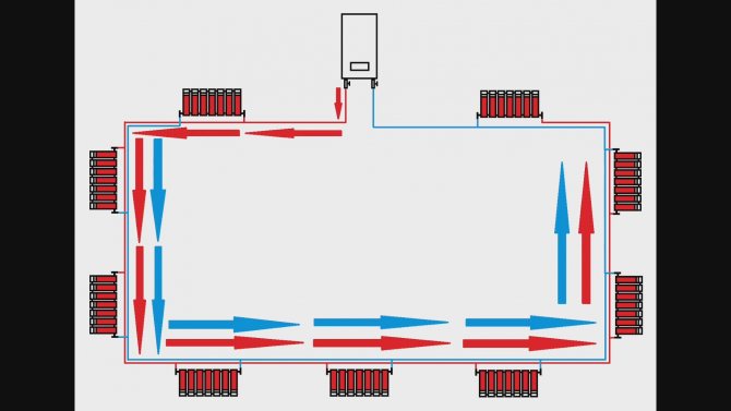
The coolant does not need to turn around, it continues to move in the same direction, and from the point of view of hydraulics, this is very good. This situation can be compared to car traffic.
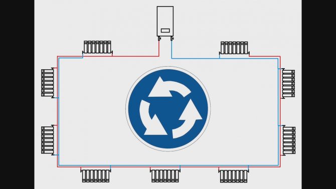
It is like a ring road without traffic lights and sharp 180 ° turns, where everything is regulated by itself. With all the advantages described, this scheme has one small disadvantage.
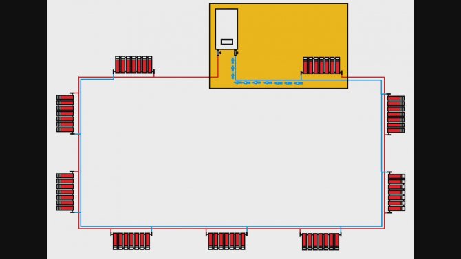
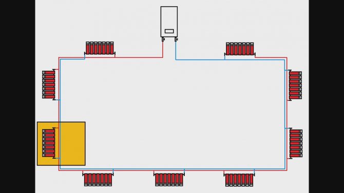
It turns out that there is a strong flow on the left, a strong return flow on the right, and somewhere in the middle, when a strong return flows into a strong flow, there is an equality of forces, and if a radiator stands in this place, it will not work.
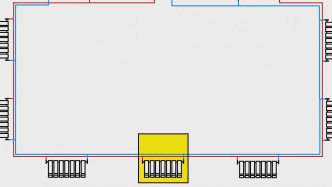
In life, this happens quite rarely, but if it happens, you can solve this problem by moving the radiator to the right or left literally 1 meter.
If you cannot move the radiator, you can extend the pipe before or after the radiator. You can make a loop like this:
After that, the radiator will heat in the same way as everyone else.
Tichelmann loop for two floors or more
Most often, such a heating system is installed in large one-story buildings. It is in such houses that she works most effectively. However, sometimes such a system is assembled in two or three-story buildings. When performing wiring in such houses, you should adhere to a certain technology. According to the Tichelman scheme, in this case, not each floor is tied separately, but the entire building as a whole. That is, an equal sum of the lengths of the return and supply pipelines for each radiator of the house is kept.
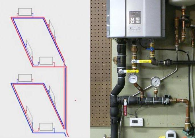
Thus, the Tichelmann loop for two floors is assembled according to a special scheme.Also, experts believe that using only one circulation pump in this case is impractical. If possible, it is worth installing one such device on each floor in the building. Otherwise, if the only pump breaks down, the heating will be turned off in the whole house at once.
Heating system diagram for the house of the Tichelman loop
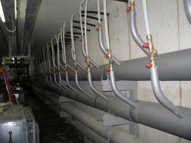
Basically, it is planned to lay the heating pipeline under the flooring in the tunnels, dressed in heat-insulating shells so as not to destroy the structures by overheating. The floors are made either on logs, or a thick screed floor heating is laid. Mainly flexible piping is used, elbow fittings are not used.
In modern houses, the Tichelman loop loses its main drawback - the complexity of laying a vicious circle on the distributor. Can be easily used in small and large areas, when installed under the floor. Recently, floor convectors have been increasingly used under high windows.
One of the most popular types of heating systems in our time is the so-called Tichelman loop. This scheme is quite simple, but when performing wiring in this case, of course, you need to adhere to a certain technology. Before installing such a system, it is imperative to draw up a detailed project, having made all the necessary calculations. The Tichelmann loop heating circuit is actually very simple. In this case, the supply pipe is pulled in the usual way - that is, from the boiler to the last radiator.
The Tichelman loop will turn out to be a suitable circuit for connecting convectors, more economical and stable compared to the ray circuit with a large number of more than 4 pieces. Private houses are always of a compressed layout, there are no long lines to heating devices, - there is no increased hydraulic resistance in the circuits.
Recommendations to make calculations of the heating system are unnecessary, since the exact heat loss of the building cannot be independently established, and the equipment used is standard, it remains only to choose the appropriate one from a couple of samples.
To determine the diameter of the pipes for the Tichelman loop, you can use the tabular data, the dependence of the diameter on the required energy. With heat losses up to 15 kW m sq.
Application area
They are also used for the main highways in most cases, up to about 8 radiators in a ring. With heat losses from 15 to 27 kW up to square meters. The diameter of the piping in the loop can be reduced as calculated. And with the condition indicated above.
What is the system and how is it installed
In any case, a minimum diameter of 16 mm is laid to the last radiator according to the flow. For heated area up to sq. M. It is advisable to make a common riser and lay a separate Tichelman loop ring for each floor. It is important to take into account that the energy losses for each floor will differ significantly, in accordance with this, the selection of radiators is made, as well as the diameter of the pipes.
Separate floor plans will allow one floor to be balanced against another and greatly simplify system setup. It is only important not to forget to include a balancing crane in the loop for each floor.
Areas of application of the Tichelman hinge
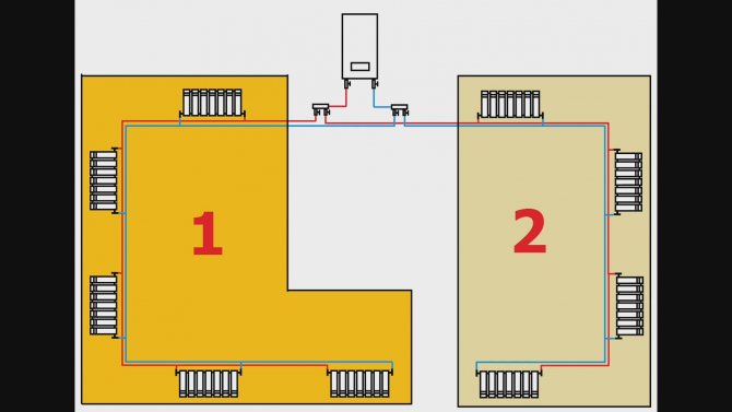
The increased consumption of materials is not always better, therefore, the Tichelman system in a two-story house is rarely used. The exception is the highway with the placement of radiators around the perimeter of the building. The ring system will require significant costs for materials, but the arrangement of the closed ring is carried out only in the absence of interference in the form of doorways, windows "to the floor". We'll have to lay another line to return the coolant to the heating device.
If the loop is lengthened, moved away from the heater, the pipe cross-section is increased, or a powerful circulation pump is selected, otherwise the system will not be able to work at full capacity.
To reduce the flow rate of the coolant in the area where the first batteries are connected, the diameter of the pipeline should be reduced, this will help maintain the water pressure in subsequent sections. Reducing the diameter is carried out only according to preliminary calculations, otherwise the radiators located at a considerable distance from the heating device will not receive the coolant in sufficient volume.
It turns out that it is possible to use two-pipe wiring with a passing water flow only with a total length of the line of 70 meters, on which it is installed from 10 radiators. Otherwise, the associated wiring will not justify the investment.
System Description
In professional circles, the Tichelman loop is called a two-pipe heating system with a passing movement of the coolant. This name fully reflects the essence and principle of operation, the distinctive features are best seen against the background of a two-pipe system with a reverse movement of the coolant, which is familiar to almost everyone.
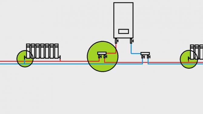
Imagine a radiator network deployed in a straight line. In the classical scheme, the heating unit is located at the beginning of this row, from it along the entire network follow two pipes for supplying hot and returning cold coolant, respectively. At the same time, each radiator is a kind of shunt, therefore, the further the heater is removed from the heating unit, the higher the hydraulic resistance in the loop of its connection.
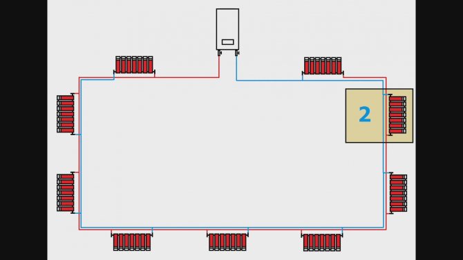
1 - Two-pipe connection diagram for radiators with a countercurrent coolant in the supply and return; 2 - connection diagram Tichelman loop with passing connection
If we roll a row of radiators into a ring, then both of its edges will adjoin the heat unit. In this case, it is much more profitable to make sure that the return pipeline does not send the coolant back to the boiler room, but continues to follow the chain, that is, along the way. In other words, the supply pipe follows from the heating unit and ends at the extreme radiator, in turn, the return pipe originates from the first radiator and goes to the boiler room. The same principle can be implemented even if the radiators are located linearly in space, simply from the place where the extreme radiator is inserted into the return pipe, the pipe unfolds to return the cooled coolant. At the same time, in a certain area, the heating system will be three-pipe, as the Tichelman loop is also sometimes called.
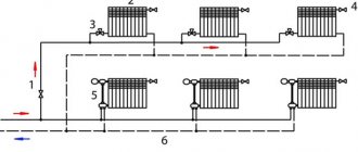
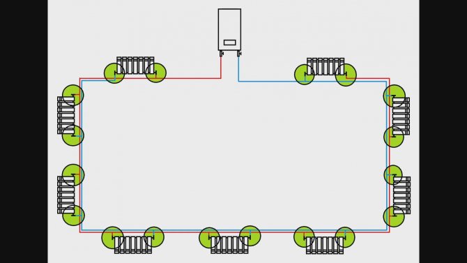
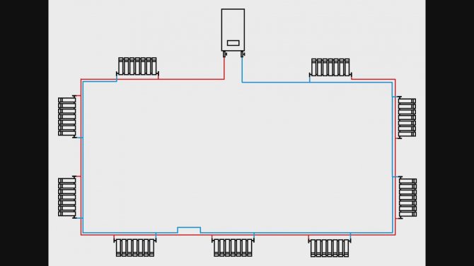
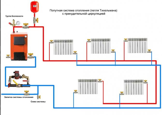
Tichelman loop with the placement of radiators along the perimeter of the building. From each radiator, the total length of the supply and return pipes is approximately the same. 1 - heating boiler; 2 - security group; 3 - heating radiators; 4 - supply pipe; 5 - return pipe; 6 - circulation pump; 7 - expansion tank
But why are such complications necessary? If you carefully study the diagram, it turns out that the sum of the lengths of the supply and return pipelines for each radiator is the same. Hence the conclusion: the hydraulic resistance of each individual connection loop is equivalent to the rest of the sections, that is, the system simply does not need balancing.
What is Tichelman's loop
The Tichelman loop (also called a "passing scheme") is a piping diagram of a heating system. Such a scheme combines the advantages of two common schemes at the same time: the Leningrad and two-pipe, while having additional advantages.
When compared with a two-pipe scheme, when using the Tichelman loop, there is no need to install expensive control systems. The heaters work like one large radiator. The coolant flow is the same throughout the heating circuit.There are no pipe constrictions and dead-end radiators, in which the duct is worst of all. The disadvantage in comparison with a two-pipe heating scheme is that the entire branch must be made with a large diameter pipe, which can greatly affect the cost of the entire system as a whole.
If we compare it with the Leningrad (one-pipe) scheme, the advantage is that the coolant does not pass through the pipe past the radiator. The Leningrad circuit is very demanding on the circuit design and installation. With a low qualification of performing either the first or the second, it will be impossible to force the water to pass through the heater, it will pass through the pipe by. The radiator will remain slightly warm. In addition, in the Leningrad scheme, the first radiators in terms of water flow will be hotter than the subsequent ones. Since the water reaches them already chilled. The disadvantage of the Tichelman loop in comparison with the "Leningrad" loop is that the pipe consumption is almost doubled.
Of the general advantages, I would like to note that such a scheme is difficult to unbalance. The conditions for the movement of the coolant are almost ideal, which, moreover, is positively reflected in the operation of the heat generator (be it a boiler, solar systems or something else).
The main disadvantage of the associated heating scheme is certain requirements for the room. In practice, it is not always possible to organize the circular movement of the coolant. Doorways, architectural features, etc. may interfere. In addition, it can be used only with horizontal wiring; with a vertical Tichelman loop, it is not applicable.
Tichelmann hinge: scheme for private houses
Tichelmann loop pipe diameter
The diameters in the Tichelman loop are selected in the same way as in a two-pipe dead-end heating system. Where the flow rate is greater, there is also a larger diameter. The farther from the boiler, the lower the flow rate can be.
If you choose the wrong diameters, then the average radiators will not heat well.
More about the program
If an artificial hydraulic resistance to the radiator branches is not created in the pressure heating system, then medium radiators will not heat well either.
What conditions must be observed in the Tichelman loop in order for medium-sized radiators to heat well?
Each radiator branch must have a hydraulic resistance equal to 0.5-1 Kvs. This resistance can be given by a thermostatic or balancing valve, which is placed on the radiator line. As a rule, when savings are made on thermostatic and balancing valves (that is, they are not installed), then each radiator branch begins to have a low hydraulic resistance, which is comparable to if you simply connected the supply and return with a pipe (Roughly made a bypass).
Note:
For gravitational heating systems with natural circulation, the radiator branches do not need to create artificial resistance. Because due to the natural pressure of the coolant, the radiator branch itself affects its consumption.
The Tichelmann loop can be used without a pump, but only with large diameters, as is done for gravitational heating systems with natural circulation. And to calculate the diameters, the heating system simulator program will help you: More about the program
How to choose the diameters in the Tichelman loop?
The diameters in the Tichelman loop are not an easy task, as is the choice of diameters in a two-pipe dead-end heating system. The principle of choosing the diameters depends on the flow rates and head losses in the pipeline.
Below you will see how the diameters are selected.
Bad Tichelmann loop chains
Medium radiators will work poorly if there is no artificial hydraulic resistance on the radiator branches. Artificial resistance is created by balancing or thermostatic valves. For which the throughput is 0.5 - 1.1 Kvs.
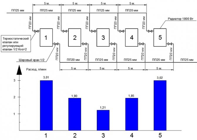
Pressure heating system with ball valves and polypropylene pipe 20 mm.
You can't do this on ball valves:
Such a radiator branch has a low hydraulic resistance. She will eat up a lot of consumption and there will be little left for other radiators.
A chain for 5 radiators with a 25mm PP main pipe was tested.
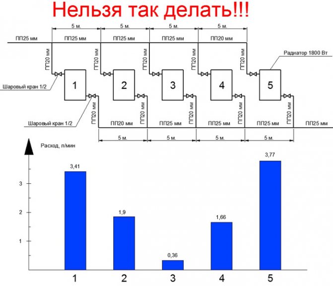
Radiator costs are not the same. The third radiator has the smallest flow rate. This is due to the fact that there are ball valves on the radiator branches.
If thermostatic valves are added to the circuit, then the costs become more equally divided:
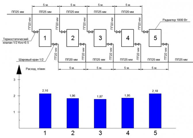
The picture is already better! But the diameters can be reduced in some places and save on this. For example, on the supply line up to 4 radiators and on the return line from 2 radiators.
If we try to leave PP20mm on the entire highway, we will get the following costs.
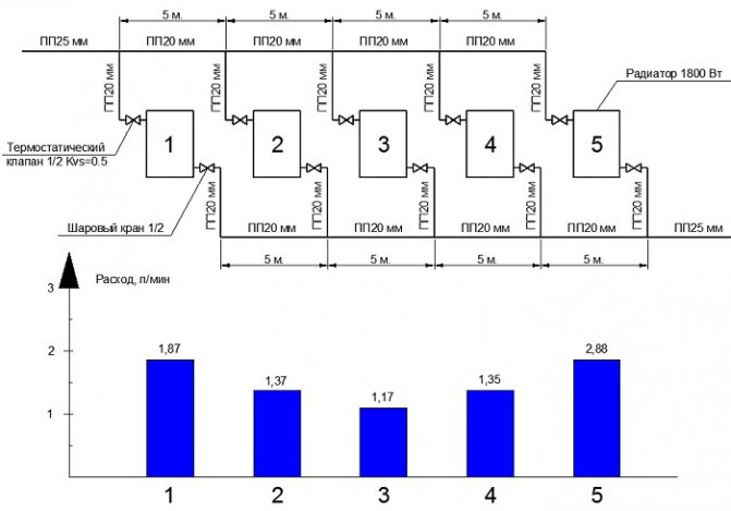
If we were to use a thermal valve or any regulating device for 2 Kvs, then the change in diameters would have to be done!
Because if someone turns on the tap completely, it will prevent other radiators from working properly. There are 5 Kvs control valves for radiators. Well, if you wake up to twist the lower valve to reduce the throughput, then do this adjustment. Of course, it will be better to use closed balancing valves, which will not be accessible to unauthorized people.
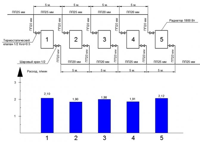
In order to improve the separation of costs for 5 radiators with the use of control valves with a larger flow capacity, it is necessary to use pipes PP32, PP25 and PP20.
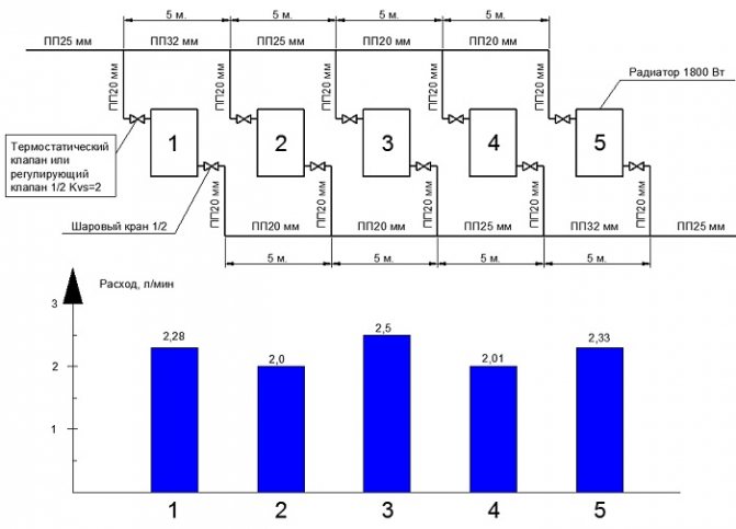
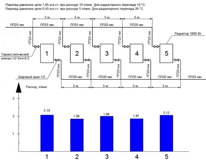
Nice Tichelmann loop chains
Diameter selection criteria:
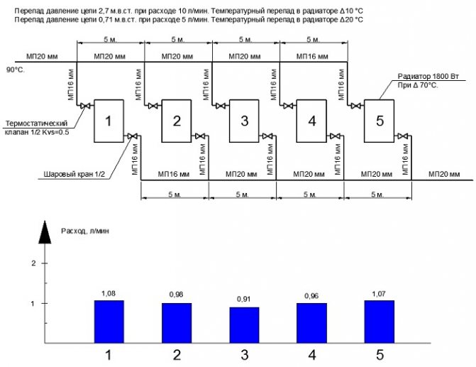
The choice of diameters for the Tichelman loop was chosen based on the chain drop of a maximum of 1 m.w. The temperature difference of the radiators is 20 degrees. The inlet temperature is 90 degrees. The difference in the output power between the radiators does not exceed 200 W. The difference in temperature differences between the radiators does not exceed 5 degrees.
Note:
The diameters indicated do not apply to low temperature heating systems. For low-temperature systems, it is necessary to reduce the temperature difference to 10 degrees and this requires a twofold increase in flow.
I prepared chains of Tichelman loops for 5 and 7 radiators for metal-plastic and polypropylene pipes.
5 radiators polypropylene pipe, Kvs = 0.5.
5 radiators, metal-plastic pipe, Kvs = 0.5.
7 radiators polypropylene pipe, Kvs = 0.5.
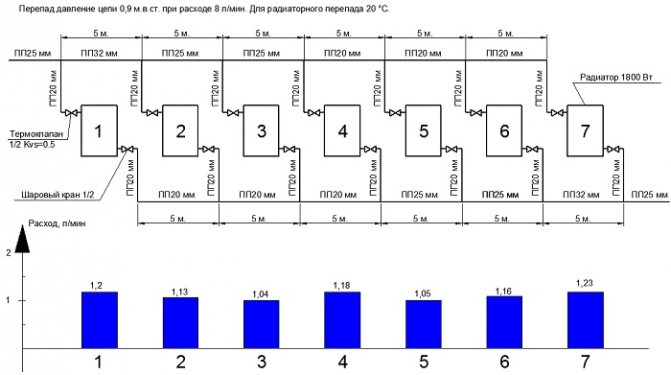
This chain uses PP32 mm. If you put the balancing valve on the radiator 1 and 7, then you can change the pipe from PP32 to PP26 mm. It is necessary to tighten the balancing valves on radiators 1 and 7.
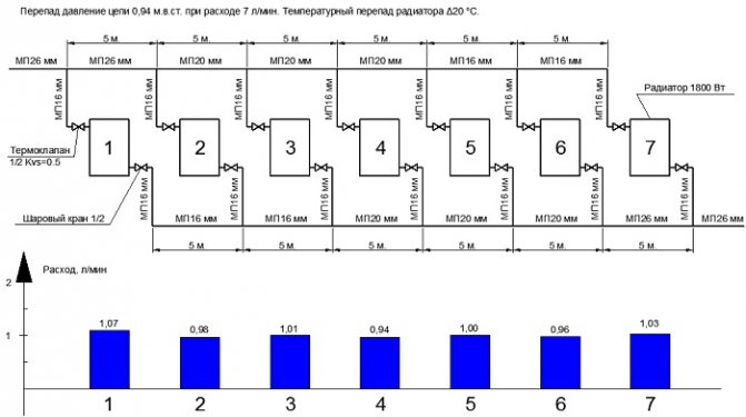
7 radiators, metal-plastic pipe, Kvs = 0.5.
The diameter selection tests were carried out in the heating simulator program.
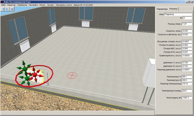
More about the simulator program
The program is used to test heating systems before being installed on site. It is also possible to test existing heating systems to improve the performance of an existing heating system.
If you need calculations of diameters for your heating system for 10 radiators, then apply for calculation services here: Order a calculation service
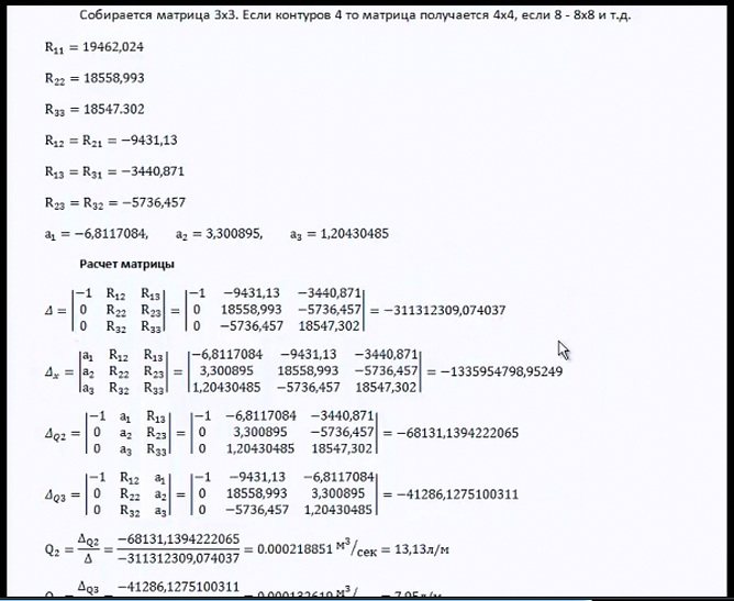
Calculation of the Tichelmann loop
As in a two-pipe dead-end heating system, diameters also have to be selected based on the flow rate and head loss of the coolant. The Tichelmann loop is a complex chain and the mathematical calculation becomes much more complicated.
If in a two-pipe dead-end the chain equation looks simpler, then for the Tichelman loop the chain equation looks like this:
More information about this calculation is described in the video course on the calculation of heating here: Video course on the calculation of heating
How to set up a Tichelman loop? How to set up a passing heating system?
As a rule, the Tichelman loop has conditions when average radiators do not heat well, in this case, as in a dead-end duct, we clamp the balancing valves on the radiators located closer to the boiler. The closer the radiators are to the boiler, the tighter we squeeze.
A series of video tutorials on a private house
Part 1. Where to drill a well? Part 2. Arrangement of a well for water Part 3. Laying a pipeline from a well to a house Part 4. Automatic water supply
Water supply
Private house water supply. Principle of operation. Connection diagram Self-priming surface pumps. Principle of operation. Connection diagram Calculation of a self-priming pump Calculation of diameters from a central water supply Pumping station of water supply How to choose a pump for a well? Setting the pressure switch Pressure switch electrical circuit Principle of operation of the accumulator Sewerage slope for 1 meter SNIP
Heating schemes
Hydraulic calculation of a two-pipe heating system Hydraulic calculation of a two-pipe associated heating system Tichelman loop Hydraulic calculation of a single-pipe heating system Hydraulic calculation of a radial distribution of a heating system Diagram with a heat pump and a solid fuel boiler - logic of operation Three-way valve from valtec + thermal head with a remote sensor Why does the heating radiator in a multi-apartment building do not heat well? home How to connect a boiler to a boiler? Connection options and diagrams DHW recirculation. Principle of operation and calculation You do not correctly calculate the hydraulic arrow and collectors Manual hydraulic calculation of heating Calculation of a warm water floor and mixing units Three-way valve with a servo drive for DHW Calculations of DHW, BKN. We find the volume, power of the snake, warm-up time, etc.
Water supply and heating constructor
Bernoulli's equation Calculation of water supply for apartment buildings
Automation
How servos and 3-way valves work 3-way valve to redirect the flow of the heating medium
Heating
Calculation of the heat output of heating radiators Radiator section Overgrowth and deposits in pipes worsen the operation of the water supply and heating system New pumps work differently ... connect an expansion tank in the heating system? Boiler resistance Tichelman loop pipe diameter How to choose a pipe diameter for heating Heat transfer of a pipe Gravitational heating from a polypropylene pipe
Heat regulators
Room thermostat - how it works
Mixing unit
What is a mixing unit? Types of mixing units for heating
System characteristics and parameters
Local hydraulic resistance. What is CCM? Throughput Kvs. What it is? Boiling water under pressure - what will happen? What is hysteresis in temperatures and pressures? What is infiltration? What are DN, DN and PN? Plumbers and engineers need to know these parameters! Hydraulic meanings, concepts and calculation of heating systems circuits Flow coefficient in a one-pipe heating system
Video
Heating Automatic temperature control Simple top-up of the heating system Heating technology. Walling. Underfloor heating Combimix pump and mixing unit Why choose underfloor heating? Water heat-insulated floor VALTEC. Video seminar Pipe for underfloor heating - what to choose? Warm water floor - theory, advantages and disadvantages Laying a warm water floor - theory and rules Warm floors in a wooden house. Dry warm floor. Warm Water Floor Pie - Theory and Calculation News to Plumbers and Plumbing Engineers Are you still doing the hack? First results of the development of a new program with realistic three-dimensional graphics Thermal calculation program. The second result of the development of Teplo-Raschet 3D Program for thermal calculation of a house through enclosing structures Results of the development of a new program for hydraulic calculation Primary secondary rings of the heating system One pump for radiators and underfloor heating Calculation of heat loss at home - orientation of the wall?
Regulations
Regulatory requirements for the design of boiler rooms Abbreviated designations
Terms and Definitions
Basement, basement, floor Boiler rooms
Documentary water supply
Sources of water supply Physical properties of natural water Chemical composition of natural water Bacterial water pollution Requirements for water quality
Collection of questions
Is it possible to place a gas boiler room in the basement of a residential building? Is it possible to attach a boiler room to a residential building? Is it possible to place a gas boiler room on the roof of a residential building? How are boiler rooms divided according to their location?
Personal experiences of hydraulics and heat engineering
Introduction and acquaintance. Part 1 Hydraulic resistance of the thermostatic valve Hydraulic resistance of the filter flask
Video course
Download the Engineering Calculations course for free!
Calculation programs
Technotronic8 - Hydraulic and thermal calculation software Auto-Snab 3D - Hydraulic calculation in 3D space
Useful materials Useful literature
Hydrostatics and hydrodynamics
Hydraulic Calculation Tasks
Head loss in a straight pipe section How does head loss affect flow rate?
miscellanea
Do-it-yourself water supply of a private house Autonomous water supply Autonomous water supply scheme Automatic water supply scheme Private house water supply scheme
Privacy Policy
Traditionally used heating schemes
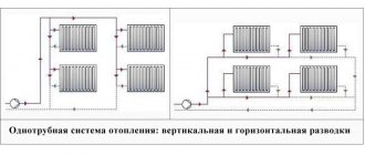
- One-pipe. The circulation of the heat carrier is carried out through one pipe without the use of pumps. On the line, the radiator batteries are connected in series, from the very last through the pipe the cooled medium is returned to the boiler (“return”). The system is simple to implement and economical due to the need for fewer pipes. But the parallel movement of streams leads to a gradual cooling of the water, as a result, to the radiators located at the end of the series chain, the carrier arrives significantly cooled. This effect increases with an increase in the number of radiator sections. Therefore, in rooms located near the boiler, it will be excessively hot, and in remote rooms, it will be cold. To increase heat transfer, the number of sections in the batteries is increased, different pipe diameters are installed, additional control valves are installed, and each radiator is equipped with bypasses.
- Two-pipe. Each radiator battery is connected in parallel to the pipes for the direct supply of the hot coolant and the “return”. That is, each device is supplied with an individual outlet to the "return". With the simultaneous discharge of cooled water into the common circuit, the coolant returns to the boiler for heating. But at the same time, the heating of heating devices also gradually decreases as they move away from sources of heat supply. The radiator located first in the network receives the hottest water and is the first to give the carrier to the “return”, while the radiator located at the end receives the coolant as the last one with a reduced heating temperature and also gives water to the return circuit as the last. In practice, in the first appliance, the hot water circulation is the best, and in the last one it is the worst. It is worth noting the increased price of such systems in comparison with one-pipe systems.
Both schemes are justified for small areas, but ineffective with long networks.
An improved two-pipe heating scheme is Tichelman. When choosing a specific system, the determining factor is the availability of financial capabilities and the ability to provide the heating system with equipment that has the optimal required characteristics.
Tichelman heating feature
The idea of changing the principle of operation of the "return" was substantiated in 1901 by the German engineer Albert Tichelman, in whose honor it got its name - "Tichelman loop". The second name is “reversible type return system”.Since the movement of the coolant in both circuits, supply and return, is carried out in the same, concurrent direction, the third name is often used - “scheme with concomitant movement of thermal carriers”.
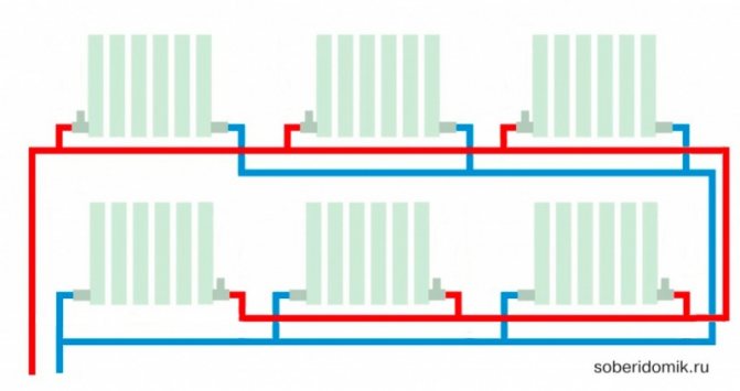
The essence of the idea consists in the presence of the same length of straight and return pipe sections connecting all radiator batteries with a boiler and a pump, which creates the same hydraulic conditions in all heating devices. Circulation circuits of equal length create conditions for the hot coolant to pass the same path to the first and last radiators with the same thermal energy being received by them.
Tichelman loop diagram: