- Follow Google+ Facebook twitter
Rss
Modern heating systems have a fundamentally different approach to regulation - this is not a setup process before starting with subsequent operation in a constant hydraulic mode, these are systems with a constantly changing thermal regime during operation, which, accordingly, requires equipment to track these changes and respond to them. New approaches, solutions, materials and designs in heating systems develop these already highly complex and dynamic systems. In these conditions, specialists must be proficient in the variety and specifics of the use of modern control valves for the implementation of high-tech and energy-efficient heating systems with optimized capital costs.
Tasks and sequence of hydraulic calculation of the heating system
Hydraulic calculation, along with the use and correct installation of control valves in modern heating systems, is a guarantee of efficient operation.
The main points of the efficient operation of the heating system are:
- the supply of coolant to heating devices in an amount sufficient to ensure the thermal balance of the premises with a changing outside air temperature and a user-specified indoor air temperature (within the limits of the room standardized for a given functional purpose); minimization of operating costs, including energy costs, to overcome the hydraulic resistance of the system; minimization of capital investments in the construction of a heating system, depending, inter alia, on the adopted pipe diameters; noiselessness, reliability and stability of the heating system.
To ensure the compliance of heating systems with the listed requirements, the following tasks should be solved, which are implemented in the process of hydraulic calculation:
determine the diameters of pipelines in sections of the heating system, taking into account the recommended and economically feasible speeds of movement of the coolant; calculate hydraulic pressure losses in sections of the system; perform hydraulic balancing of parallel instrumental and other branches of the system, using control valves for dynamic balancing during non-stationary thermal and hydraulic operating modes of the heating system; determine the pressure loss and flow rate of the heating agent in the heating system.
Hydraulic calculation is the most difficult, time consuming and important stage in the design of water heating systems. Before carrying out it, the following computational and graphic works must be performed:
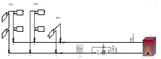
- the heat balance of the heated premises has been determined; the type of heating devices or heat exchange surfaces was selected and their placement in the heated rooms was carried out on the building plans; fundamental decisions were made on the configuration of the water heating system (placement of the heat source, routing of main pipelines and instrument branches), the type of pipelines used, shut-off and control valves (valves, taps, valves and pressure regulators, flow rate, thermostats); a diagram of the heating system is drawn (preferably axonometric) with an indication of the number, heat loads and lengths of the calculated sections; the main circulation ring is determined - a closed loop, which includes successive sections of pipelines with a maximum flow rate of the heat carrier from the source of thermal energy to the most distant heating device (for a two-pipe system) or an instrument branch-riser (for a one-pipe system) and back to the heat source.
The calculated section of the pipeline is a section of constant diameter with a constant flow rate of the coolant, determined by the heat balance of the premises.The numbering of the calculated sections begins from the heat source (ITP or heat generator). The nodal points at the branch points on the supply main pipeline, as a rule, are designated by capital letters of the alphabet; in the corresponding nodes on the prefabricated main pipelines, they are indicated with a stroke.
Get full text
Tutors
Unified State Exam
Diploma
The nodal points at the branch points of the distribution device branches (risers) are designated by Arabic numerals, which correspond to the floor number in horizontal systems or the number of the device branch-riser in vertical systems; in the nodes for collecting coolant flows, these numbers are indicated with a prime. The number of each calculated section consists of two letters or numbers that correspond to the beginning and end of the section.
The numbering of instrument branches (risers) in vertical heating systems is recommended to be performed in Arabic numerals clockwise along the perimeter of the building, starting from the apartment located in the upper left part of the floor plan.
The lengths of the sections of pipelines of the heating system with an accuracy of 0.1 m are determined according to plans drawn to scale.
The heat load of the calculated section is equal to the heat flux that must transfer (on the supply pipelines) or transferred (on the return pipelines) the coolant that is transported on the section. The heat load of the calculated sections of the system of main distribution and prefabricated pipelines with rounding to 10 W is calculated after applying the heat load to all heating devices and instrument branches. As a rule, the heat load of the calculated area Qi-j
, W, indicate above the extension line, and the length of the section
li-j
in meters - under the extension line.
Knowing the amount of heat on i-j
-section of the heating system
Qi-j
- which transports the coolant with temperatures in
tg
serving and
to
in the return pipelines, you can determine the required flow rate of the heating medium in the corresponding sections of the heating system
(1)
Where: from
= 4.2 kJ / (kg ° C) - specific heat capacity of water;
tg
- design temperature of the hot coolant in the heating system, ° С;
to
- design temperature of the cooled heat carrier in the heating system, ° С.
Program overview
For the convenience of calculations, amateur and professional hydraulics calculation programs are used.
The most popular is Excel.
You can use the online calculation in Excel Online, CombiMix 1.0, or the online hydraulic calculation calculator. The stationary program is selected taking into account the requirements of the project.
The main difficulty in working with such programs is the lack of knowledge of the basics of hydraulics. In some of them, there are no decoding of formulas, the features of branching of pipelines and the calculation of resistances in complex circuits are not considered.
- HERZ C.O. 3.5 - calculates using the method of specific linear pressure loss.
- DanfossCO and OvertopCO - can count natural circulation systems.
- "Flow" (Potok) - allows you to apply the calculation method with a variable (sliding) temperature difference across the risers.
It is necessary to clarify the parameters for entering data on temperature - in Kelvin / Celsius.
· Decrease in system performance (increase in thermal inertia).
To ensure the minimization of capital costs according to the second economic condition - the diameters of pipelines and fittings should be the smallest, but not leading, at the design flow rate of the coolant, to the appearance of hydraulic noise in the pipelines and shut-off and control valves of the heating system, which occur at values of the coolant velocity of 0.6-1 , 5 m / s depending on the value of the coefficient of local resistance.
Obviously, with the opposite direction of the above requirements for the size of the determined diameter of the pipeline, there is a region of reasonable values of the speed of movement of the coolant.As the experience in the construction and operation of heating systems, as well as a comparison of capital and operating costs, shows, the optimal range of values for the speed of movement of the coolant is in the range of 0.3 ... 0.7 m / s. In this case, the specific pressure loss will be 45 ... 280 Pa / m for polymer pipelines and 60 ... 480 Pa / m for steel water and gas pipes.
Taking into account the higher cost of pipelines made of polymer materials, it is advisable to adhere to higher speeds of the coolant movement in them to prevent an increase in capital investments during construction. At the same time, operating costs (hydraulic pressure losses) in pipes made of polymeric materials will be less or remain at the same level in comparison with steel pipes due to a significantly lower value of the coefficient of hydraulic friction.
Get full text
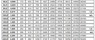
To determine the inner diameter of the pipeline dvn
at the calculated section of the heating system with a known transported heat flow and temperature difference in the supply and return pipelines
∆tco
= 90 - 70 = 20 ° C (for two-pipe heating systems) or the flow rate of the heat carrier, it is convenient to use Table 1.
Table 1. Determination of the inner diameter of pipelines of the heating system
The further choice of pipelines for engineering life support systems, including heating, is to determine the type of pipe that, under the planned operating conditions, will provide maximum reliability and durability. Such high requirements are explained by the fact that pipelines for hot and cold water supply systems, heating, heat supply systems for ventilation and air conditioning, gas supply and other engineering systems pass through almost the entire volume of the building.
table 2

The cost of pipelines of all engineering systems in comparison with the cost of the building is less than 0.1%, and an accident or replacement of pipelines when their service life is less than the service life of the building leads to significant additional costs for cosmetic or major repairs, not to mention the possible losses in case of an accident for restoration equipment and material values in the building.
All industrial pipes used in heating systems can be divided into two large groups - metallic and non-metallic. The main distinguishing feature of metal pipes is mechanical strength, non-metal pipes are durability.
Based on the predetermined internal diameter of the pipeline, the corresponding nominal diameter is taken dy
for metal pipes or outside diameter and pipe wall thickness
dн x s
for polymer (metal-polymer) pipelines.
Different types of pipes have different mechanical, hydraulic and operational characteristics, which have different effects on the processes of hydrodynamics and the distribution of heat flows in the heating system.
It is known that with a decrease in the hydraulic losses of friction pressure during the movement of the coolant in the pipes, the efficiency of regulating the coolant flow (heat flow) of the heating device increases due to the increase (redistribution) of the actuated available pressure on manually or automatically controlled valves, taps, valves or other fittings. In this case, they speak of an increase in the authority of the control valve. The authority of the control valve should be understood as the fraction of the pressure located in the regulated section, which is spent on overcoming the local resistance of the valve (valve) when the coolant moves.
How to work in EXCEL
The use of Excel tables is very convenient, since the results of hydraulic calculations are always reduced to tabular form. It is enough to define the sequence of actions and prepare exact formulas.
Input of initial data
A cell is selected and a value is entered. All other information is simply taken into account.
- the D15 value is recalculated in liters, so it is easier to perceive the flow rate;
- cell D16 - add formatting according to the condition: "If v does not fall within the range 0.25 ... 1.5 m / s, then the background of the cell is red / the font is white."
For pipelines with a difference in inlet and outlet heights, static pressure is added to the results: 1 kg / cm2 per 10 m.
Presentation of results
The author's color scheme carries a functional load:
- Light turquoise cells contain raw data - you can change it.
- Pale green cells - constants to be entered or data that are little subject to change.
- Yellow cells - auxiliary preliminary calculations.
- Light yellow cells - calculation results.
- Fonts: blue - initial data;
- black - intermediate / non-main results;
- red - the main and final results of the hydraulic calculation.
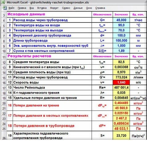
Results in Excel table
Example from Alexander Vorobyov
An example of a simple hydraulic calculation in Excel for a horizontal pipeline section.
- pipe length 100 meters;
- ø108 mm;
- wall thickness 4 mm.

Local resistance calculation results table
By complicating step-by-step calculations in Excel, you better master the theory and partially save on design work. Thanks to a competent approach, your heating system will become optimal in terms of costs and heat transfer.